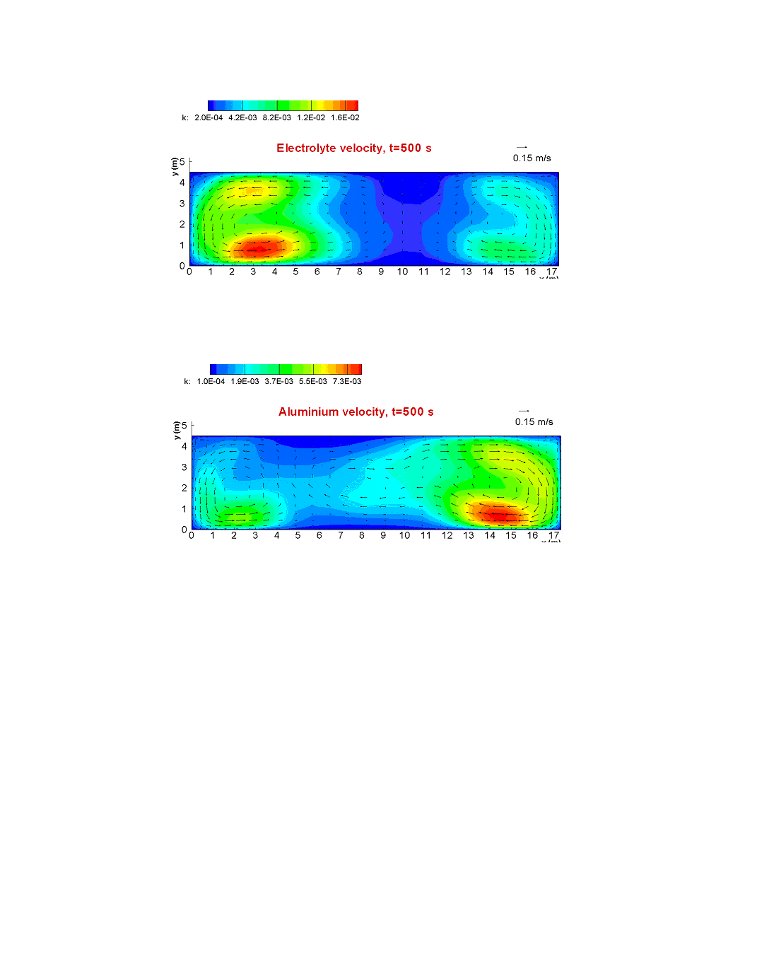
Figure 7 - Velocity pattern and turbulent kinetic energy k distribution in the electrolyte layer
Figure 8 - Velocity pattern and turbulent kinetic energy k distribution in the aluminium layer
cells are very stable even without any additional stabilizing measures. For the end cells we
attempt to introduce the selective collector bar rodding (shown in Figure 1) in order to
reduce the horizontal currents in the metal pad. The MHD model is more sensitive to the 3-
dimensional nature of the external bar connection, which leads to clearly visible bottom
current increase at the metal bottom where the rodding is applied. The resulting horizontal
currents in the metal are indeed considerably reduced (Figure 10). The horizontal velocity
patterns are changed, also, and made almost similar in both liquid layers (Figures 11 and 12).
The metal pad surface is more flat (Figures 13 and 14) than without the selective collector