bar rodding (compare to Figures 5, 6). The small `dips' seen in the Figures 13, 14 are created
because the aluminium vortices are slightly more intense than in the electrolyte for this case.
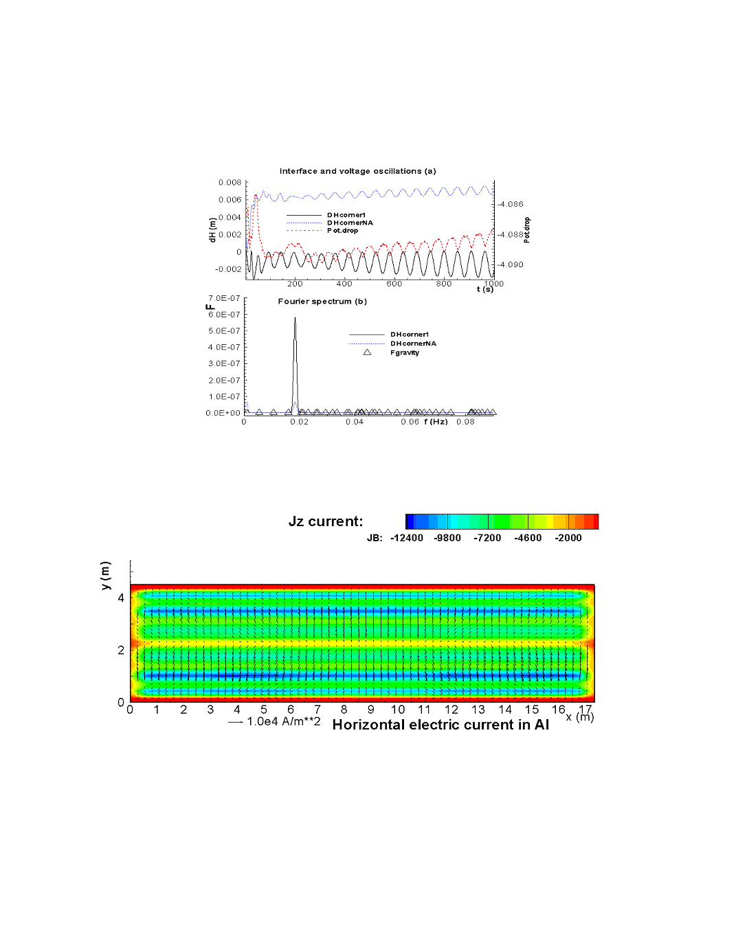
Figure 9 (a) Liquid metal pad and cell voltage oscillations for the standard case without
selective collector rodding; (b) Fourier power spectra for the pad oscillations.
Figure 10 Electric current distribution in the aluminium layer with selective collector
rodding