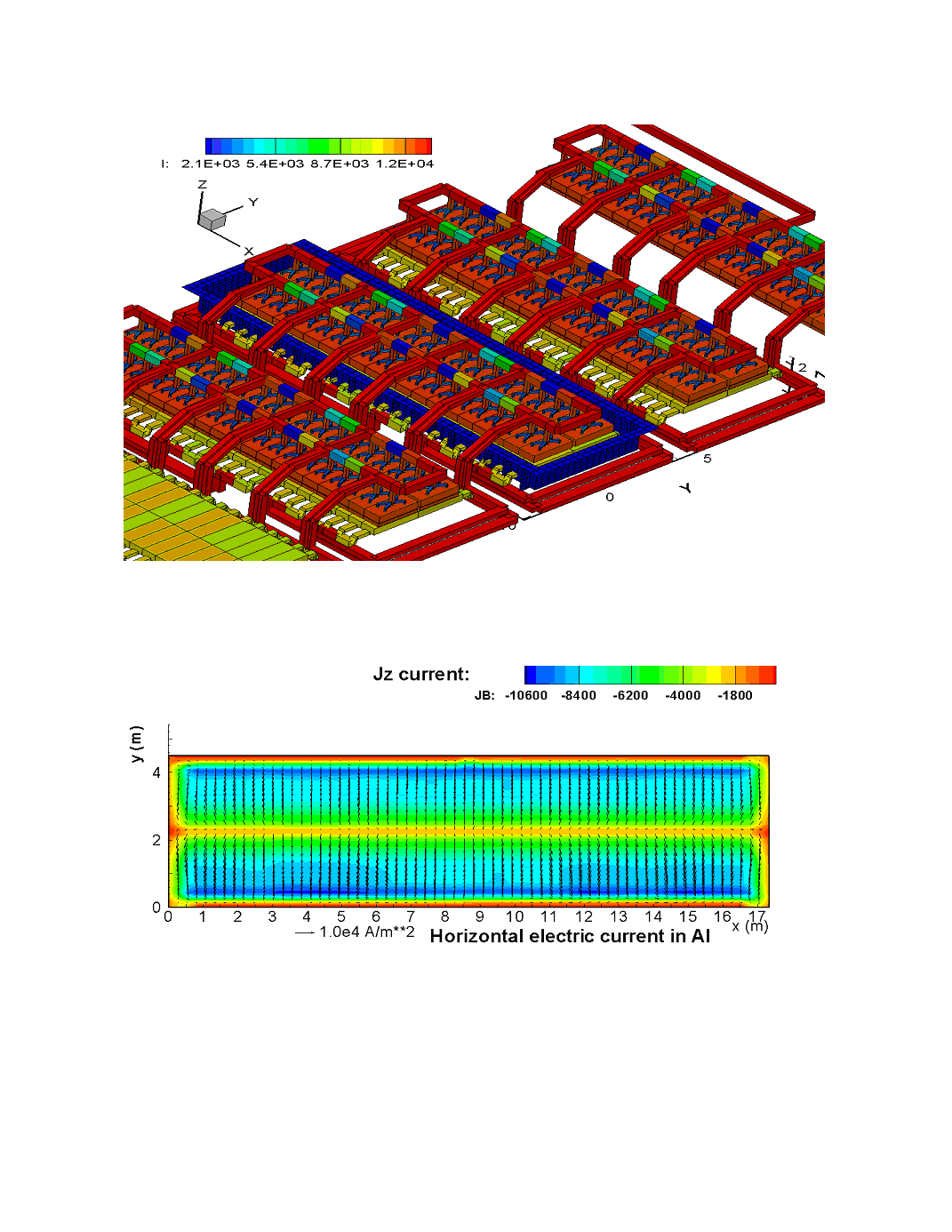
Figure 3 The bus bar network and the electric current distribution for the 500 kA cell
positioned close to the line end. The test cell contains also the ferromagnetic
parts for the magnetic field prediction
Figure 4 Electric current distribution in the aluminium layer for the standard case without
selective collector rodding