DESIGNING CELLS FOR THE FUTURE -WIDER AND/OR EVEN HIGHER
AMPERAGE?
Marc Dupuis, Jonquière
Barry Welch, Auckland
The present approach of simply increasing the length of cells as we move to higher amperage has
introduced operational issues. However, as recently presented, the existence of copper collector bar
technology opens the door to designing cathode that extracts
100% of the current directly on the
downstream side. It also obviously opens the door to designing wider cell without generating harmful
horizontal current in the metal pad and increasing the cathode voltage drop. This design alternative is
explored here and spectacular benefits are apparent while practical operating issues are minimised.
Introduction
The modern aluminium smelting industry is faced with several challenges, limitations and the availability
of clean green energy supply necessary for metal production, a greater need to efficiently use the resources
available, and simultaneously reduce the capital and operating costs while meeting more stringent
environmental control requirements. Since the advent of point feeders a singular approach to cell design
has been used to address these challenges namely increasing the length of the cell, although operating
benefits have also been derived from such features as alumina conveying systems, and use of more
intelligent point feeder breaking devices [1, 2]. More recently limitations arising from lengthening the cells
have become apparent from both capital cost and operating performance [3]. The reduction in liquid bath
volume combined with the higher amperage load per point feeder has accentuated the spatial variations
within the cell, and in some situations giving rise to almost continuous co-evolution of perfluorocarbons as
a consequence of temperature and alumina concentration gradients within the cell [4, 5, 6].
The benefits of increasing the amperage through length of the cells in reducing the heat loss steadily
diminishes an almost an exponential decay, while for modern operations and work practices the process
energy required for the typical work practices and quality of raw materials only varies in a narrow range
between 6.5 and 6.65 kWh per kilogram [7], so future reductions in energy consumption are dependent on
designs that can lead to lower heat loss. However as recently presented, copper collector bar technology
opens the door to designing cathode that extracts 100% of the current directly on the downstream side.
Such a design change also opens the door to designing wider cell without generating harmful horizontal
current in the metal pad and increasing the cathode voltage drop. This design alternative would also open
the door to reducing the heat loss per unit production and also increasing the productivity of the potroom by
minimising the wasted space associated with the cell to cell interconnection.
Criteria applied to new designs
In this paper the successful advanced models already developed [8, 9,10] have been applied to basic cell
design when fitted with anodes that enable the width to be extended and hence the active electrode area per
unit cell length increased. It also looks to applying the reversed compensation current (RCC) busbar
concept, and utilising the benefits of utilising a greater proportion of strategically positioned copper in the
collector bars. When originally proposed in 2011 [10], it was speculative but it is no longer since Storvik
AS [11] presented technology for casting copper inserts into steel at ISCOBA
2015 conference.
Furthermore, more recently KAN-NAK advocated that copper collector bars do not even need to be
protected by steel shell and rodded to the block with cast iron [12].
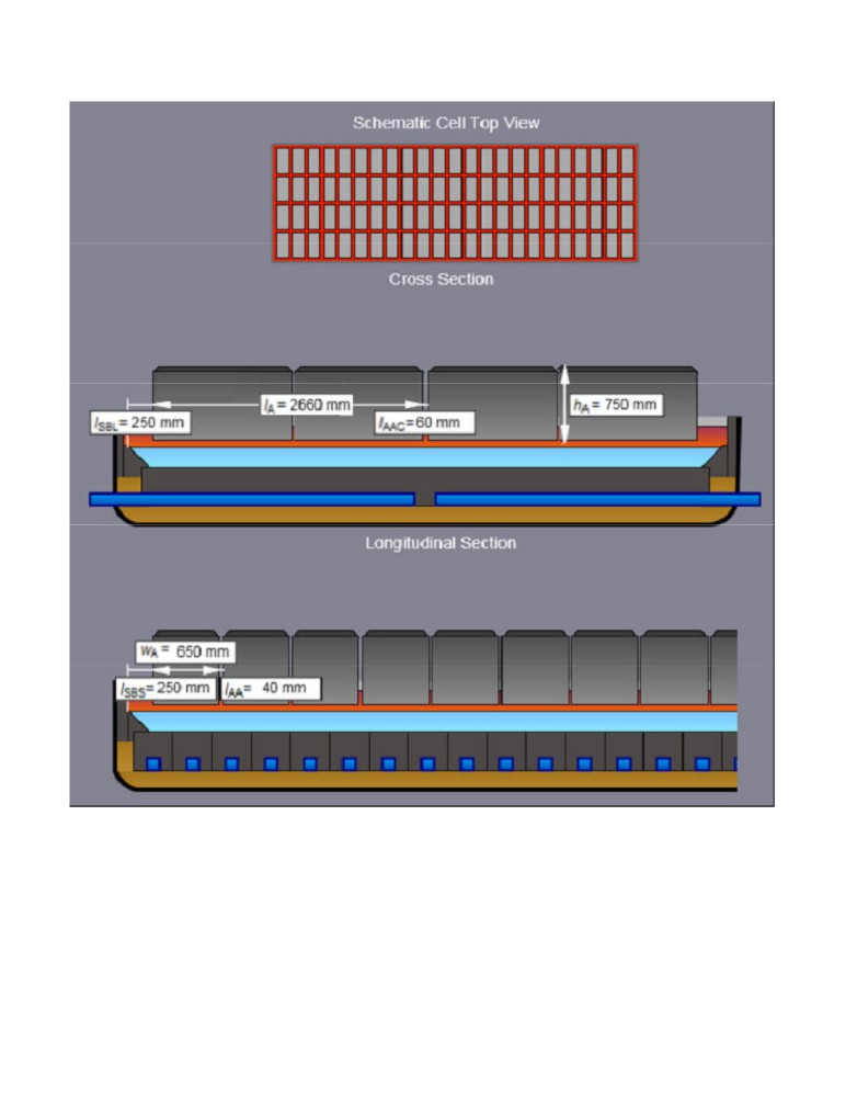
The key features of the anode designs envisioned in this analysis are as for each anode rod supports two
carbon blocks of a standard width and height but arranged end on end giving and total overall length of
2.66 m. However the gap between the two anodes would be wide enough to form a channel of electrolyte
approximately 6 cm wide to enhance electrolyte flow and mixing of the alumina. With strategic anode
design refinements it would also enable the channels to be used for alumina feeding to further minimise
concentration gradients thus minimising spatial problems and lowering the risk of PFC co-evolution. A
central channel would also be maintained. Furthermore at amperages above approximately 700 kA, the
consumption rate of alumina opens the way for more innovative feeding.
The two cell designs modelled requires approximately 5.4 meters long cathodes blocks for the anode design
described, while the modelling design outputs presented are based on the cells operating with a nominal
current density 0.94 A/cm2 , superheat of 10°C, and 15 cm depth of anode cover material.
The first cell design evaluated has internal dimensions of the cavity
17.02 m long by 5.88 m wide and this
would be fitted with 48 anode assemblies giving rise to an operating current of 762 kA. Figure 1 presents
the anode layout and a cross-section of the cathode.
The second 1 MA design maintains the width of the cell, but the length would be extended to a similar
length to width aspect ratio currently applied in most designs.
The 760 kA cell.
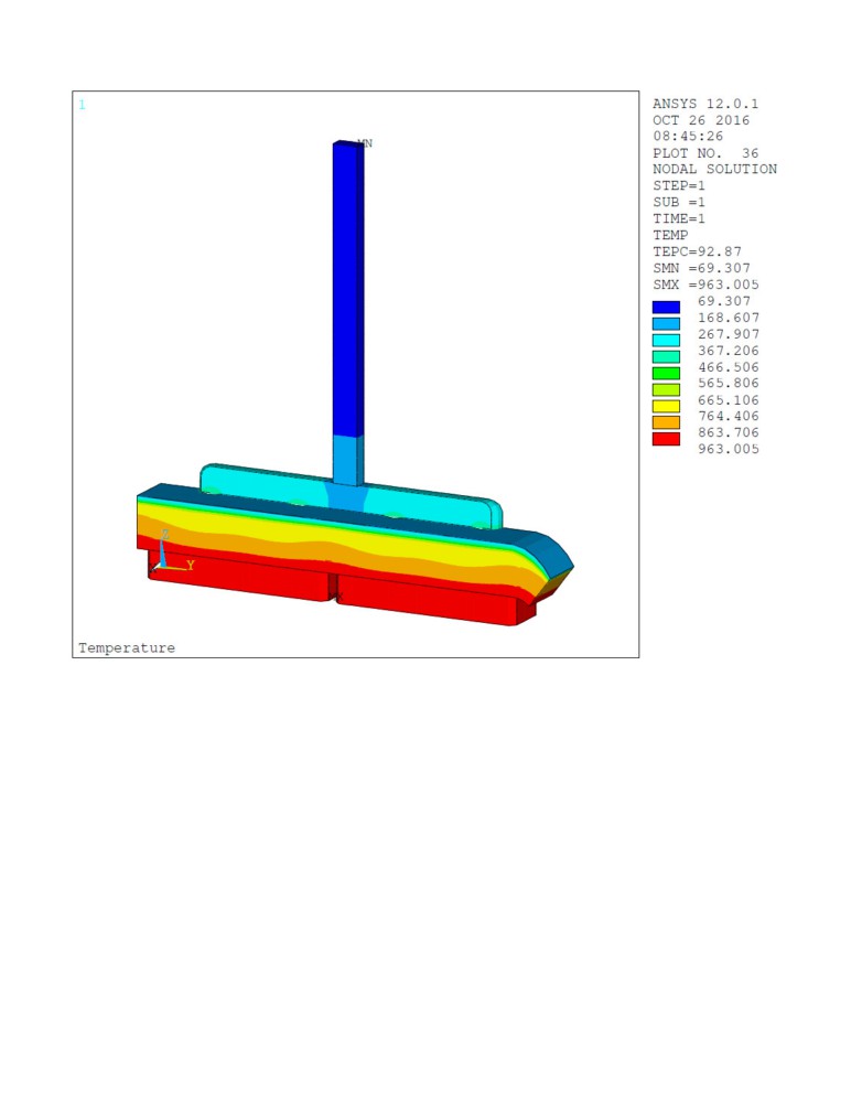
Figure 2 presents the thermal profile of the wide anode while the figure 3 presents the voltage solution.
Each anode assembly is predicted to have a resistance of 22 µΩ giving a voltage drop of 347 mV at 0.94
A/cm2 anodic current density. Calculations are based on two stubs per block each with a diameter of 21 cm.
Like the anode presented in [10], that anode is using the anode stub hole design presented recently [13]. An
anode panel made of 48 such anode would dissipate 550 kW with 15 cm of a typical anode cover material.
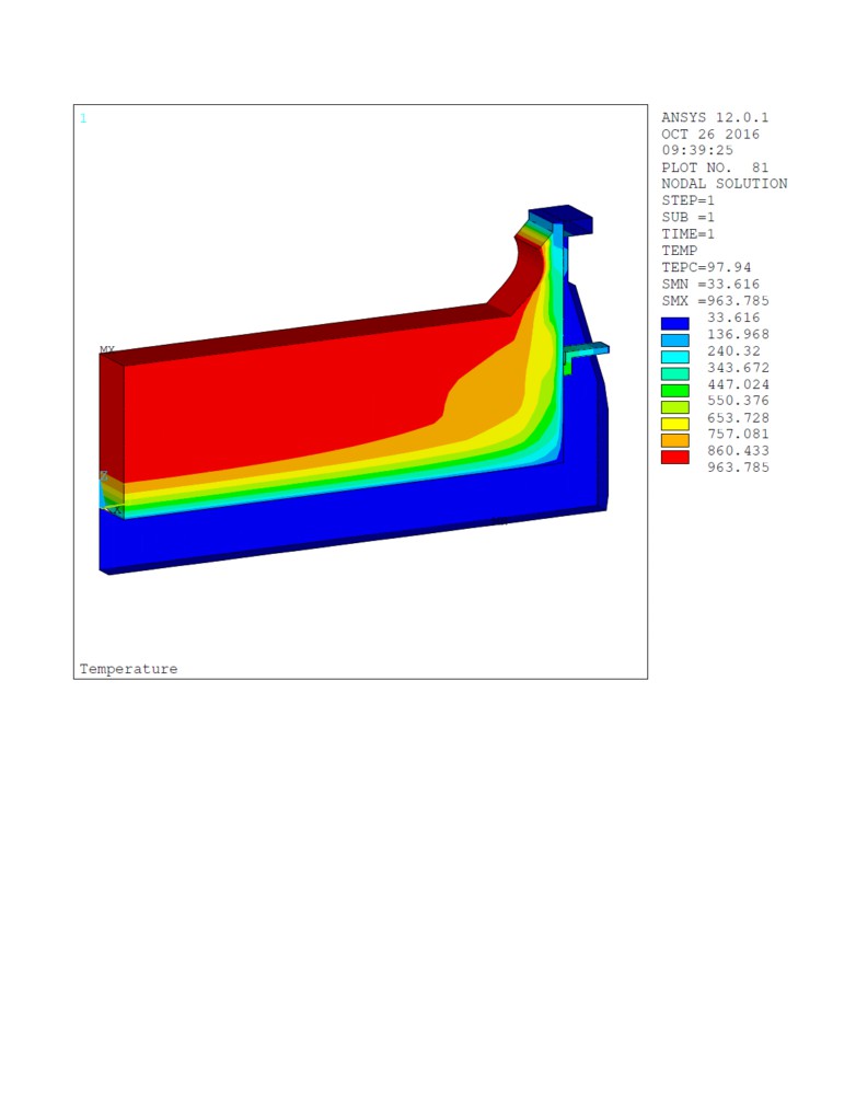
Figure 4 presents the thermal profile generated by the cathode side slice model. The cathode voltage drop is
predicted to be 118 mV when the cell operates at 762 kA. By assuming an operating anode to cathode
distance (ACD) of 3.0 cm and a busbar drop of 300 mV, a global cell resistance of 0.395 micro ohms is
obtained which corresponds to a cell voltage of about 4.10 V. Current efficiencies of 95% have been
achieved at similar and even slightly lower model based ACD’s. This combination of operating conditions
would correspond to comparable and achievable energy consumption of 12.8 kWh/kg. The consequential
cell heat loss would be approximately 1300 kW which is consistent with both the thermodynamic dynamics
of the process and the modelling output for the proposed anode cover depth.
Benefits of the RCC busbar concept design.
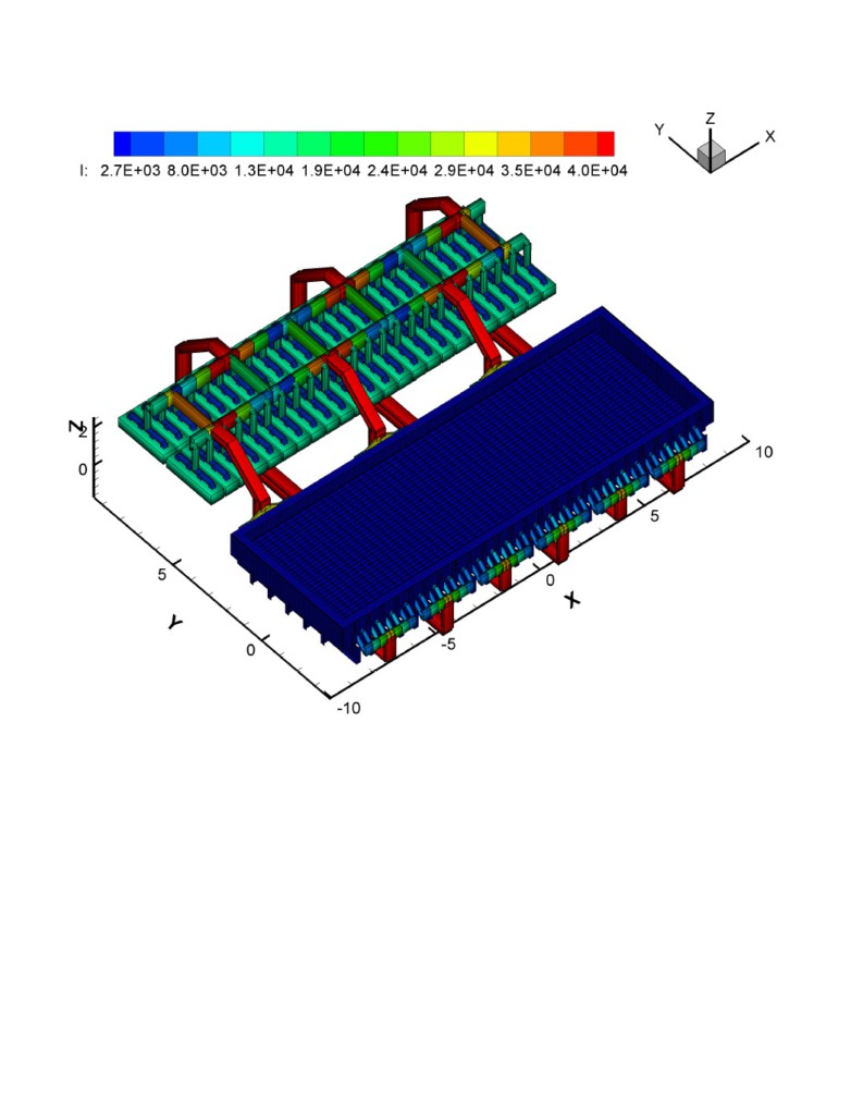
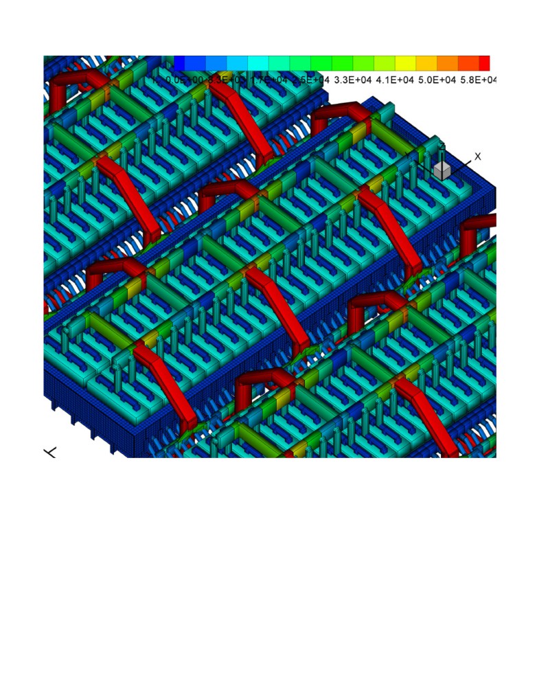
The reversed compensation current (RCC) busbar concept used in the modelling incorporates alternating
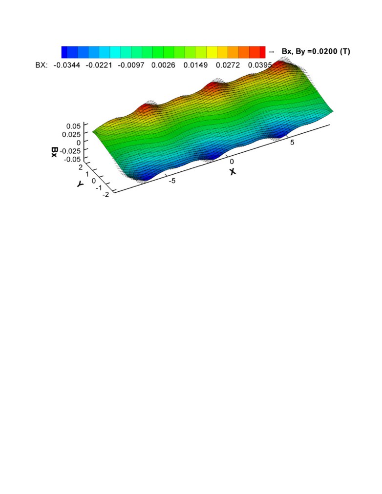
upstream and downstream anode risers. This is illustrated in figures 5 and 6. This configuration helps to
produce anti-symmetric longitudinal magnetic component (Bx) which in turn produces a symmetric bath-
metal interface deformation. It also helps by producing a metal flow circulation that should promote
alumina dissolution and minimize the risk of sludge formation [14, 15]. An added benefit is that it helps
reduce the busbar weight by enabling a reduced cell to cell distance. The cell to cell distance achieved in
this study is 7.6 meters. This has the dramatic benefit of increasing the productivity of the potroom by
significantly more than 10 % through the reduction of the proportion not filled with electrodes.
Since the original proposals for the RCC concept [16], the alternating upstream and downstream anode
risers innovation has been combined with a second innovation, a cathode concept where 100% of the
current is extracted by copper collector bars located on the downstream side of the potshell. Copper
collector bars have been shown to allow this kind of design for regular width cell [14, 15]. Also copper
collector bars permit the design of wider cell if regular cathode designs with equal upstream/downstream
current extraction are used.
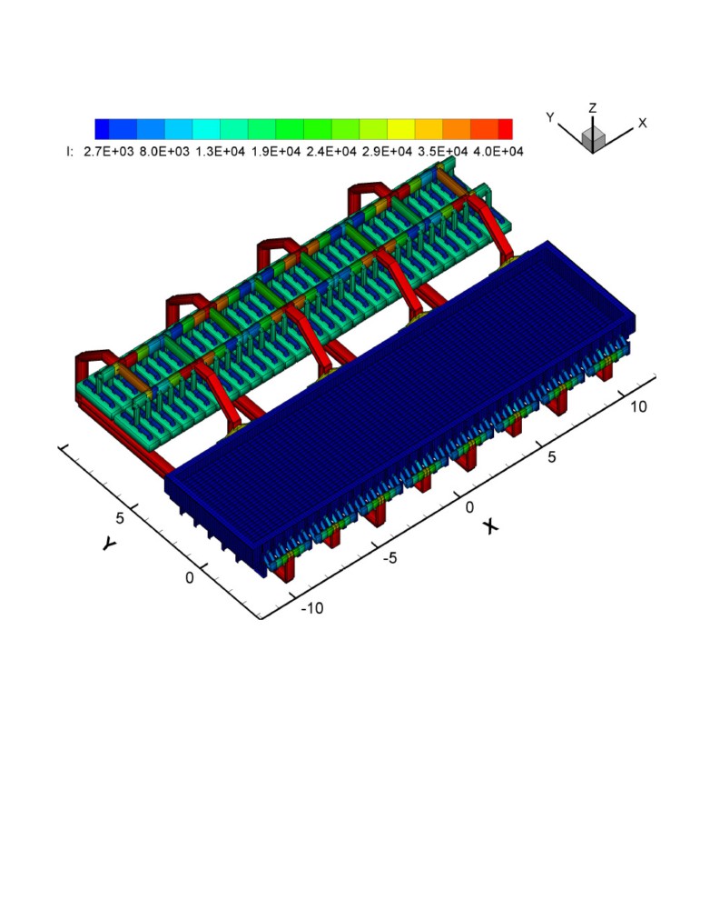
The present study presents of the first time results of such a RCC busbar concept design with alternating
upstream and downstream anode risers applied to a regular yet wider cathode design. Again, figure 5 is
presenting the busbar layout for a single cell without the compensation busbar. Globally, all the potline
current is passing in cathode busbar located under the cell. The compensation busbars are located in tandem
under those cathode busbars, they are also passing the full potline current but in the opposite direction.
Figure 6 is presenting the full potline busbar layout.
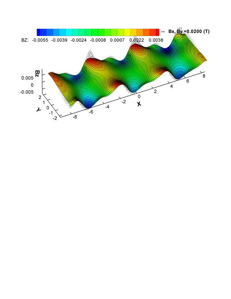
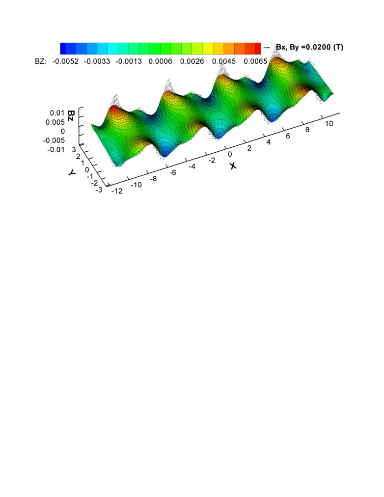
Figure 7 is presenting the resulting vertical component of the magnetic field (Bz) while figure 8 is
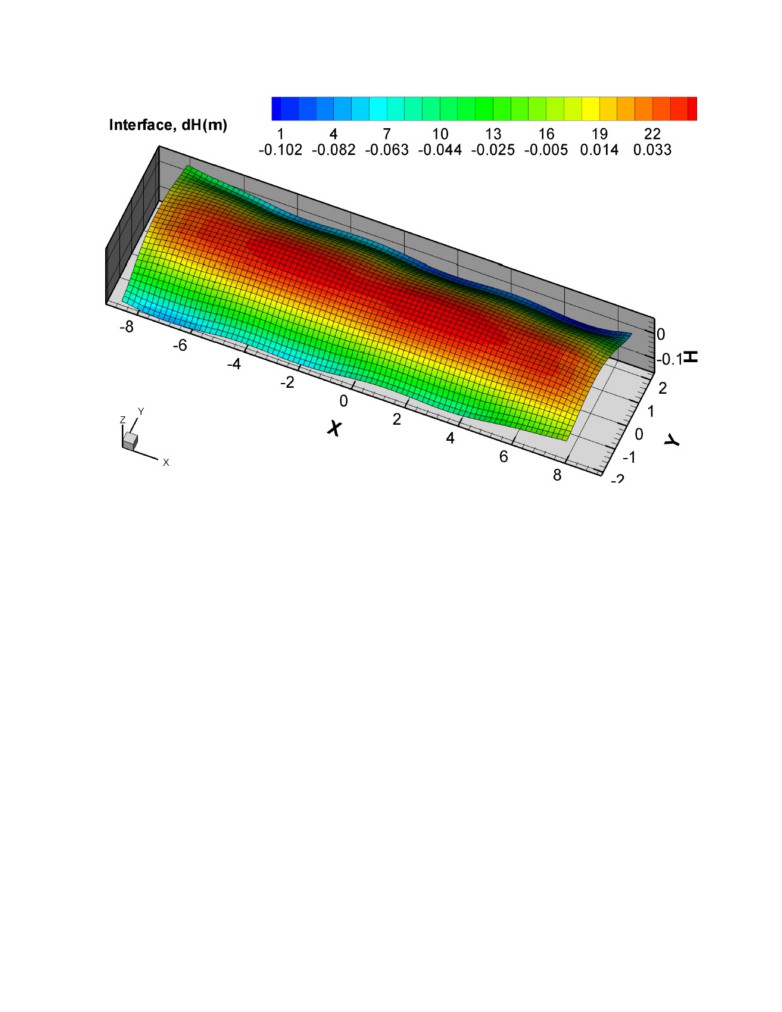
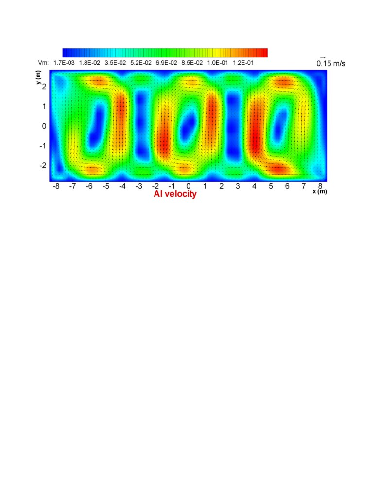
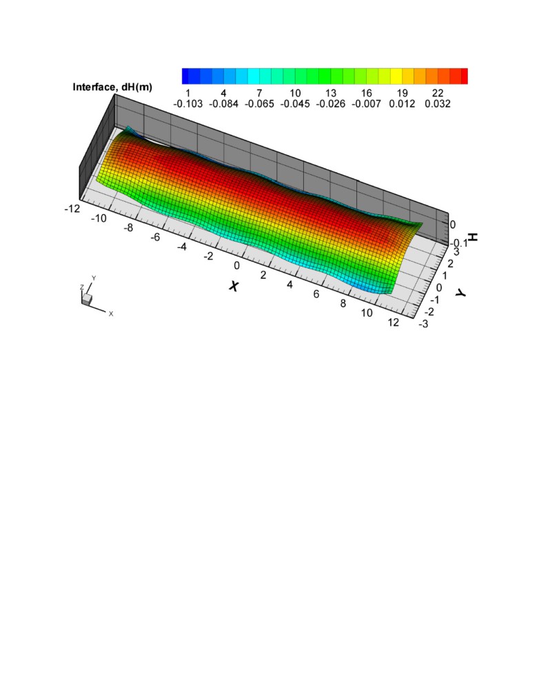
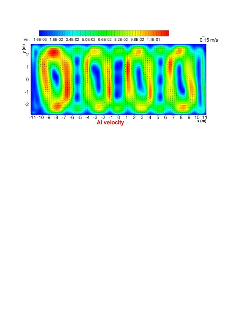
presenting the obtained Bx. Figure 9 is presenting the bath-metal interface deformation while figure 10 is
presenting the metal flow. Globally those results are quite good.
Extrapolation to a longer 1 MA cell
As previously demonstrated in [16], the RCC busbar concept is applicable to any cell length. The above
wider 762 kA cell has close to a 3 to 1 aspect ratio while a regular width cell of a similar amperage would
ratter have close to a 4 to 1 aspect ratio. Clearly before thinking of designing a still wider cell, it is possible
to take advantage of the RCC busbar concept to design a bigger cell this time by extending the cell length.
Figure 11 is presenting the RCC busbar layout of a 64 anodes, 8 anode risers 1 MA cell. That cell is simply
5.52 m longer that the 762 kA cell making room for 16 extra same size anodes. Figure 12 13 and 14 present
the corresponding Bz, bath-metal interface and metal flow solutions demonstrating once again that the
RCC busbar concept is directly applicable to any cell length. At that new cell length, we are back to close
to a 4 to 1 aspect ratio.
Discussion and Conclusions
Several clear advantages of the combination of RCC, increasing the width of the shell, and simultaneously
increasing the number of channels for a distributed alumina feeding system become apparent from the
modelling outputs.
From an operational perspective, the combination of the fairly flat metal pad at such a high current density,
and the presence of risers on either side of the cell will minimise the adverse upstream that verses
downstream swing in the metal pad that occurs during regular anode change. This would enable even lower
anode cathode distances if the cell heat balance permits. A reduction in the tendency for low energy cells to
form spikes and other anode protrusions would be another consequence. It is noted that there are three very
conservative figures used in this modelling and energy balance calculations that can be readily changed to
enable further energy reduction. These are the external bus bar resistance which can be reduced by
increasing the mass of material used through an increased cross-sectional area, the ability to increase the
number of stubs in each anode block to lower the resistance, and the use of strategic insulation on zones of
the pot shell that will both increase the ease of operation and lower heat loss.
Environmentally the cell will also have the potential to perform much better. The new anode and
superstructure design features enable introduction of features that can minimise the spatial variations in
temperature and alumina concentration which are the root cause of the low level of perfluorocarbons that
are coevolved in the long narrow high amperage cells. At the proposed current the average alumina
consumption rate will exceed 8 kg per minutes and as demonstrated by Andrews [17] these mass-flow rates
enable accurate control and metering. So when combined with a distributed feeding system has the
potential of eliminating sludge formation.
Managing the longer anode presents a potential downside if the anode-change work practice continues to be
reliant on the multipurpose cranes. However it has been pointed out [18] that robotic systems have the
potential for incorporation into the anode change work practice that would overcome such obstacles - and
such a change is desire desirable if waste heat and energy associated with the process is being used to pretty
the incoming anodes.
Consequently the outputs presented for the innovative practical design features modelled here demonstrate
the changes open the door to a potential step forward. Reductions in capital and operating costs of
greenfield smelters are likely while the cells would give new benchmark levels of environmental
performance
References
[1] Roald Hvidsten and Ketil Å. Rye “Smart Feeders for Alumina in a Hall-Héroult Prebake”, Light Metals
2009, 435-438.
[2] K Nikandrov, A. Zarouni, S Akhmetov, and N. Ahli. “Evolution of crust breaker control for DX+ and
DX+ Ultra technologies” Light Metals 2016, 511-514.
[3] O. Martin, R.Gariepy and G.Girault, “APXe and AP60: The New References for Low Energy and High
Productivity Cells”, 11th Australasian Aluminium Smelting Technology Conference ("AASTC"), Dubai,
UAE, 6 - 11 December 2014.
[4] D.S.Wong and J.Marks. “Continuous PFC emissions measured on Individual 400 kA Cells.” Light
Metals, 2013, 865-870.
[5] A.T. Tabereaux, “Low Voltage Anode Effects and Unreported PFC Emissions”, Proceedings of 34th
International ICSOBA Conference, Québec City, Canada, 3 - 6 October 2016, Paper AL16, Travaux No.
45, 631-641.
[6] M. R. Doreen, M. M. Hyland, R. G. Haverkamp, J. B. Metson, Ali Jassim, B. J. Welch and A. T.
Tabereaux “Co-evolution of carbon oxides and fluorides during the electrowinning of aluminium with
molten NaF-AlF3-CaF2-Al2O3 electrolytes”, Light Metals, 2017, (at Press).
[7] B. J. Welch, “Specific energy consumption and energy balance of aluminium reduction cell”, VIII
International Congress & Exhibition “Non-Ferrous Metals and Minerals”, Krasnoyarsk, Russia, 13 - 16
[8] M. Dupuis, “Thermo-Electric Design of a 740 kA Cell, Is There a Size Limit”, ALUMINIUM 81(4)
(2005), 324-327.
[9] M. Dupuis, V. Bojarevics and D. Richard, “MHD and pot mechanical design of a 740 kA cell”
ALUMINIUM 82, (2006) 5, 442-446.
[10] M. Dupuis and V. Bojarevis, “Retrofit of a 500 kA cell design into a 600 kA cell design,”
ALUMINIUM, 87 (1/2), 2011, 52-55.
[11] Dag Sverre Sæsbøe, “Storvik high conductivity anode yoke with copper core”, Proceedings of 33rd
International ICSOBA Conference, Dubai, UAE, 29 November - 1 December 2015, Paper AL23, Travaux
No. 44, 717-726.
[12] René von Kaenel and al., “Copper bars for the Hall-Héroult process”, VIII International Congress &
Exhibition
“Non-Ferrous Metals and Minerals”, Krasnoyarsk, Russia,
13
-
16 September
2016,
[13] M. Dupuis, “Presentation of a New Anode Stub Hole Design Reducing the Voltage Drop of the
Connection by 50 mV”, VIII International Congress & Exhibition “Non-Ferrous Metals and Minerals”,
Krasnoyarsk, Russia,
13
-
16
September
wQZ90LvBVF9WWWQ0LWZZdTQ/view .
[14] M. Dupuis, “A new aluminium electrolysis cell busbar network concept”, Proceedings of 34th
International ICSOBA Conference, Québec City, Canada, 3 - 6 October 2016, Paper AL39, Travaux No.
45, 883-890.
[15] M. Dupuis, “Presentation of an improved reversed compensation current (RCC) busbar concept using
less busbar weight”, VIII International Congress & Exhibition
“Non-Ferrous Metals and Minerals”,
Krasnoyarsk, Russia,
13
-
16
September
wQZ90LvBUlJRWXo3cnZmY1k/view .
[16] M. Dupuis, “A new aluminium electrolysis cell busbar network concept”, Proceedings of 33rd
International ICSOBA Conference, Dubai, UAE, 29 November - 1 December 2015, Paper AL21, Travaux
No. 44, 699-708.
[17] E.W. Andrews. “A controllable continuous mass feed system for aluminium smelter cells” PhD
Thesis, University of Auckland, pp334, March (1998)
[18] B. J Welch.”The future of aluminium smelting - continue adaptation or introduce design and operating
innovations" Proc 10th AASTC paper 4b3, Launceston Tas, (2011)
Authors
Dr. Marc Dupuis is a consultant specialized in the applications of mathematical modeling for the
aluminium industry since 1994, the year when he founded his own consulting company GeniSim Inc
(www.genisim.com). Before that, he graduated with a Ph.D. in chemical engineering from Laval University
in Quebec City in 1984, and then worked 10 years as a research engineer for Alcan International. His main
research interests are the development of mathematical models of the Hall-Héroult cell dealing with the
thermo-electric, thermo-mechanic, electro-magnetic and hydrodynamic aspects of the problem. He was also
involved in the design of experimental high amperage cells and the retrofit of many existing cell
technologies.
Dr. Barry Welch completed his Ph.D. in high temperature thermodynamics, he then spent several years
researching high-temperature extractive metallurgical processes including three years with Reynolds Metals
Company before becoming an academic at the University of New South Wales (UNSW), Aust. There he
established a research group for electrochemical extractive metallurgy from ores and oxides dissolved in
molten salts. In
1980 he accepted the Chairmanship of the Department of Chemical and Materials
Engineering at the University of Auckland, NZ, (UoA) where his group’s research broadened to high
temperature electrochemical cell design, transfer processes, dissolution kinetics and secondary processes,
emissions and energy minimisation. On becoming an Emeritus Professor in 1998 he assisted establishing
the Light Metals Research Centre at UoA before returning to UNSW as a part-time visiting Prof to
continue research while working with industry on performance optimisation and energy minimisation.
Figure 1: Sketch of a cell using 48 such anodes produced by CellVolt from Peter Entner website:
Figure 2: Anode model temperature solution
Figure 3: Anode model voltage solution
Figure 4: Cathode model temperature solution
Figure 5: RCC busbar concept design with alternating upstream and downstream anode risers for a single
762.5 kA cell
Figure 6: RCC busbar concept design with alternating upstream and downstream anode risers for a full
762.5 kA potline
Figure 7: Corresponding vertical component of the magnetic field (Bz)
Figure 8: Corresponding longitudinal component of the magnetic field (Bx)
Figure 9: Resulting steady-state bath-metal interface deformation
Figure 10: Resulting steady-state metal flow
Figure 11: RCC busbar concept design with alternating upstream and downstream anode risers for a single
1 MA cell
Figure 12: Corresponding vertical component of the magnetic field (Bz)
Figure 13: Resulting steady-state bath-metal interface deformation
Figure 14: Resulting steady-state metal flow