1.0, the heat transfer coefficient equation parameters are changing
to:
standard application of the Kirchoff's laws:
can be reproduced and the detailed convection and radiation
boundary conditions can be applied i.e. different boundary
conditions for the vertical, horizontal facing up and down surfaces
etc.
compare with the 1D model results, equation (15) have been used
to compute all the heat transfer coefficients instead of using the
standard COEF macro [11] that computes a series of heat transfer
coefficients tables using the above full set of equations based on
individual surface orientation, typical length etc. So here, for
comparison purpose only, a single heat transfer coefficient equation
is wrongly used for all the busbar external surfaces regardless of
the different surface orientations.
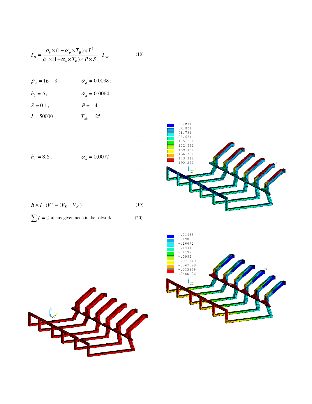
defined to be at 0 potential and the surfaces of the 12 risers in
contact with the anode beam have been coupled together in order to
be at the same potential. Figure 4 presents the obtained temperature
and figure 5 presents the obtained voltage.
busbar is 95.1 ºC and in the negative or downstream busbar is
190.2 ºC. The global busbar network voltage drop is 215 mV with
243.3 kA or 48.7% of the total 500 kA passing in the negative or
downstream side and 256.7 kA or 51.3% passing in the positive or
upstream side.