background image
ANSYS
®
model. Yet, it is important to realize that BUSNET is
creating and solving a lot more than the busbar network, it is
creating and solving the full cell network as well (see figure 8).
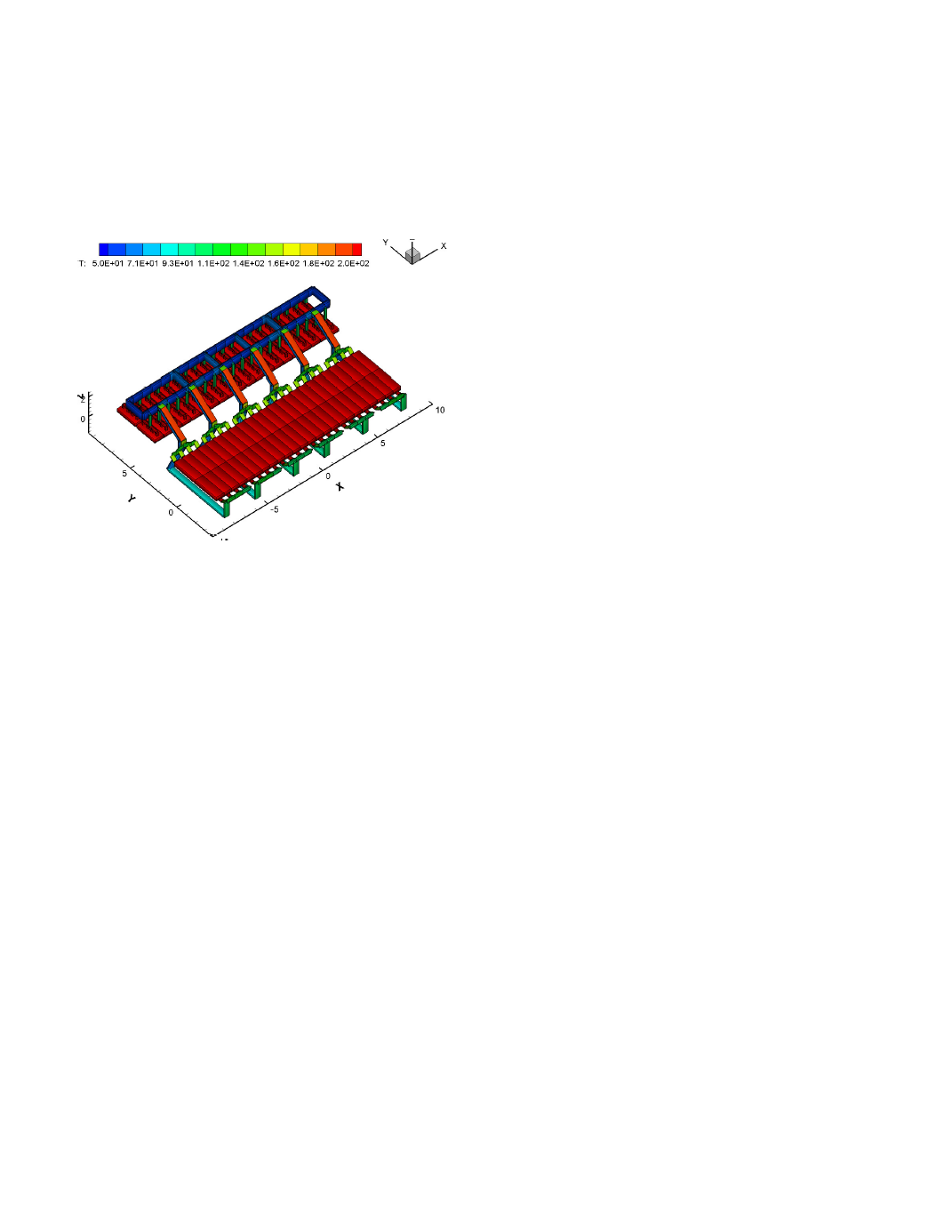
BUSNET results are as follow: the maximum temperature reached
in the positive busbar is 94ºC and in the negative busbar is 197 ºC;
the global busbar network drop is 224 mV with 247.0 kA or 49.4%
passing in the negative or downstream side and 253.0 kA or 50.6%
passing in the positive or upstream side.
Figure 8. Thermal solution of the BUSNET full cell and busbar
model.
The fact that the network current balance between the positive and
negative sides is closer to 50% 50% than both the 3D and 1D
ANSYS
®
models can easily be explained by the fact that by
modeling also the cathode blocks, BUSNET is solving the problem
more accurately because the true equipotential condition is at the
metal pad above the cathode block. If the current distribution is not
uniform between the positive and negative sides of the cell, the
potential in the cathode flexibles will not be the same between the
positive and negative sides and this of course have an impact on the
current distribution itself.
This little comparison exercise just highlighted the fact that to
accurately compute the busbar network current distribution, it is
important to consider also the cathode block resistance layer as the
two valid equipotential points are the metal pad and the anode
beam not the cathode flexibles and the anode beam.
So from that fact alone, BUSNET the 1D versatile busbar model
part of MHD-Valdis is a better tool to carry out a busbar sizing
optimization study. But this is not the only reason, BUSNET user
input file is also quite easy to edit and TECPLOT is a powerful and
easy to learn postprocessor, making BUSNET a user friendly tool
to use.
Conclusions
It was demonstrated that it is not possible to reduce a given 3D
busbar geometry into a 1D line elements network geometry without
loosing some accuracy.
It was demonstrated that the global heat transfer coefficient
between the busbar external surfaces and its surrounding has a big
impact on the busbar thermal balance. An improper setup of that
temperature dependent parameter will affect significantly the
accuracy of the model.
It was demonstrated that it is not possible to accurately compute the
busbar network current balance without including the cathode
blocks because the potential at the end of the cathode flexibles is
itself influenced by the current balance.
Finally, MHD-Valdis is the modeling tool recommended to carry
out a busbar sizing optimization study because it is very efficient,
versatile and user friendly. The maximum accuracy will be obtained
by using an ANSYS
®
based 3D full cell and external busbar model,
but that tool is not at all practical to carry out an optimization
study.
References
1. T. Tvedt and H. G. Nebell, "NEWBUS, a Simulation Program
for Calculation of the Current Distribution in the Bus Bar
System of Alumina Reduction Cells", Light Metals, TMS,
(1988), 567-573.
2. J. I. Buiza, "Electromagnetic Optimization of the V-350 Cell",
Light Metals, TMS
, (1989), 211-214.
3. M. Dupuis, "Toward the Development of a 3D Full Cell and
External Busbars Thermo-Electric Model", Proceedings of the
41
st
Conference on Light Metal, CIM
, (2002), 25-39.
4. M. Dupuis, V. Bojarevics and J. Freibergs, "Demonstration
Thermo-Electric and MHD Mathematical Models of a 500 kA
Al Electrolysis cell: Part 2", Light Metals, TMS, (2004), 453-
459.
5. M. Dupuis and V. Bojarevics, "Weakly Coupled Thermo-
Electric and MHD Mathematical Models of an Aluminium
Electrolysis Cell", Light Metals, TMS, (2005), 449-454.
6. M. Dupuis, "Thermo-Electric Design of a 740 kA Cell, is there
a Size Limit?" Aluminium 81, (2005) 4, 324-327.
7. V. Bojarevics and M.V. Romerio, "Long Wave Instability of
Liquid Metal-electrolyte Interface in Aluminium Electrolysis
Cells: a Generalization of Sele's Criterion", Eur. J. Mech.,
B/Fluids
, 13 (1) (1994), 33-56.
8. V. Bojarevics, "Non-Linear Waves with Electromagnetic
Interaction in Aluminium Electrolysis Cells", Progr. Fluid
Flow Res.: Turbulence and Applied MHD
, eds. H. Branover
and Y. Unger, AIAA, (1998), Chapter 58, 833-848.
9. M. Dupuis, V. Bojarevics and J. Freibergs, "Demonstration
Thermo-Electric and MHD Mathematical Models of a 500 kA
Al Electrolysis cell", Proceedings of the 42
nd
Conference on
Light Metals, CIM
, (2003), 3-20.
10. V. Bojarevics, "MHD-Valdis Reference Manual", Greenwich
University
, (2005).
11. M. Dupuis, "Computation of Heat Transfer Coefficient Tables
Establishing Boundary Conditions between Hot Surfaces and
their Surroundings", GeniSim Internal report, (1996).
12. M. Dupuis, A. Koshie, V. Janakiraman, S. Karthikeyan and D.
Saravanan, "Accurate Assessment of the Hirakud Smelter
Aluminium Reduction Cell Thermal Balance using only
Temperature Measurements", Proceedings of the 43
nd
Conference on Light Metals, CIM
, (2004), 525-533.
13. "TECPLOT User's Manual", Amtec Engineering, (2005),
www.tecplot.com/support/tecplot_documentation.htm