In-depth Analysis of Lining Designs for Several 420 kA Electrolytic Cells
Zhou Jianfei1 and Marc Dupuis2
1Guiyang Aluminum Magnesium Design & Research Institute, Guiyang, Guizhou, China, 550081
2GeniSim Inc., 3111 Alger St., Jonquiere, Quebec, Canada, G7S 2M9
Keywords: aluminum, smelters, 420 kA, cell lining design, cell productivity, energy efficiency, lining life, safety
Abstract
Summary and analysis on the lining areas
With the increase in market’s demand and the development of
Side wall area at liquids level
technology, high amperage electrolytic cells in China have
become widely used. In recent years, over 40 prototype cells each
The side wall area at liquids level is the key area of those four cell
operating around 420 kA have been constructed. With different
lining areas because the choice of design option and materials
electricity prices in different regions and hence different cell heat
selection determines directly the corresponding operating voltage
balance requirements, a wide variety of lining design were tested,
and cell ledge profile formation, thus influencing the process
each having its advantages and disadvantages. This study aims to
targets such as current efficiency, DC consumption, etc.
analyze and compare each lining design components in terms of
cell productivity, energy efficiency, lining life and safety aspects
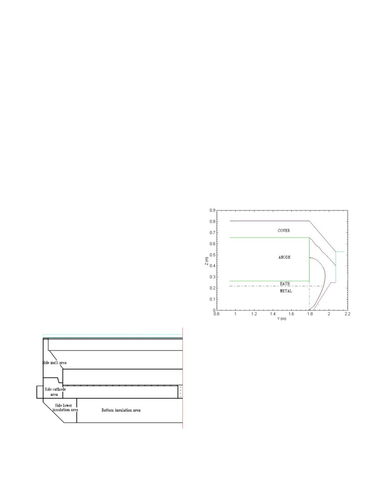
Based on experience, a reasonable side ledge profile should be as
in order to identify the most pertinent and rational design.
follow: ledge thickness at bath level around 8 to 10 cm, thickness
of ledge at metal level approx. 3 to 5 cm, ledge toe thickness
Introduction
between 5 and 8 cm and upward crust thickness, less than 15 cm
as shown in Figure 2.
Currently with increasing market demands and technology
development, GAMI’s high-amperage aluminum electrolysis cell
technology has gradually become widely used in China. In 2012-
2013, there have been 4 to 5 potlines over 400 kA put into
operation, each varying in cell lining design based on power price
variation in different areas and different process requirements. As
a result, GAMI’s 420 kA cell technology is now available with
various lining options. This study analyses and compares the
various options in order to identify the optimum design of the four
main cell lining zones from the angle of maximizing several cell
characteristics: productivity, energy efficiency, lining life and
safety aspects.
The four main cell lining zones of high amperage cell
From the design aspect, the cell lining can be divided into four
general areas: the side wall area at liquids level, the side wall area
at block level (pier region), the side wall area at lower insulation
level and the bottom insulation area, as shown in Figure 1.
Figure 2: Optimum ledge profile
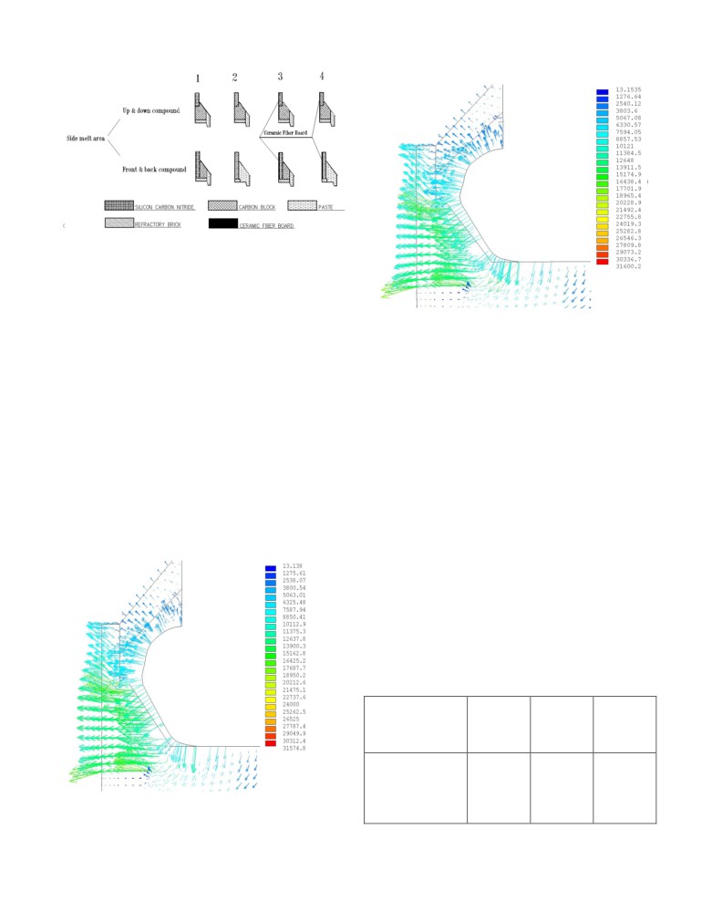
Currently the mainstream design topologies for this area cover top
& bottom material combination and front & back material
combination. There are four topologies options for each of those
two main categories as shown in Figure 3.
The difference in the top & bottom material combination option 1
and 2 is that there is silicon carbide on top and profiled carbon
block on the bottom for option 1 and carbon block on top and
profiled carbon block on the bottom for option 2. For option 3 and
4, a ceramic fiber board insulation material is added on the option
1 and 2 respectively.
The front & back option 1 uses silicon carbide in the back and
profiled carbon block in the front while option 2 uses side carbon
block in the back and ramming pastes in the front. For option 3
Figure 1: Pot lining zones [1]
and 4, a ceramic fiber board insulation material is added on the
option 1 and 2 respectively.
Figure 3: Side wall area at liquids level
These eight design options for side wall area at liquids level have
been analyzed from the angle of maximizing four cell
characteristics.
Top & bottom material combination or front & back material
Figure 5: Heat flux of side ramming paste
combination?
As it can be observed in Figures 4 and 5 above, the difference
Taking a position on this issue have been delayed for many years
between the heat flux distributions of side profiled carbon block
in China, but with the cell enlargement and low voltage
and side ramming paste is minor, so the choice of material
production trend, new understanding has been given on those two
combinations should be based on ease of construction and ledge
main design topology options.
thickness requirement.
Traditionally, the slope area is all ramming paste which is the
In general, many high amperage cells have the top hot and bottom
front & back material combination. The side profiled carbon
cold trends in different degrees, for which the top & bottom
block, which is the top & bottom material combination, has arisen
material combination has a big advantage proved in practice.
in recent years. It is more convenient for construction compared to
ramming pastes, and its heat conduction coefficient is twice that
Adding or not side wall high insulation materials?
of ramming pastes. So it has good heat dissipation potential, and
is also good for ledge formation on the slope. Taking a 420 kA
Currently, there are four high thermal insulation materials used in
cell operating at 0.78 A/cm2 as an example, the ledge thickness on
China: ceramic fiber board, nano insulation board, vermiculite
the slope of side profiled carbon blocks is 1 cm thicker than that
insulation board and hard calcium silicate board, which all have
of all ramming pastes. The details are shown in the following heat
high heat insulation performance with heat conduction
flux vector graphs of these two material combinations:
coefficients around 0.05~0.15 W/m2°C. For the present side wall
insulation engineering application, the ceramic fiber board is the
most widely used.
When the addition of high insulation materials is related with the
cell operating voltage range, the following table with 420 kA cell
operating at 0.78 A/cm2 has been produced:
Table 1
Correspondence between high side insulation materials
thickness and operating voltage
Operating voltage
4.0-4.1
3.9-4.0
3.8-3.9
(V)
High insulation
0
6
10
materials thickness
(mm)
Figure 4: Heat flux of side profiled carbon block
If the cell is operated outside the ranges specified in the above
In conclusion, the option 1 is recommended for side wall area at
table, the side ledge will be either too thick or too thin. The
block level (pier region) for cell operating over 400 kA.
former will result in increasing metal pad horizontal current which
will in turn lower the cell operating stability and make the cell
more difficult to operate. The latter can result in cell leakage thus
Adding or not side wall high insulation materials?
decreasing cell life and increasing safety risk.
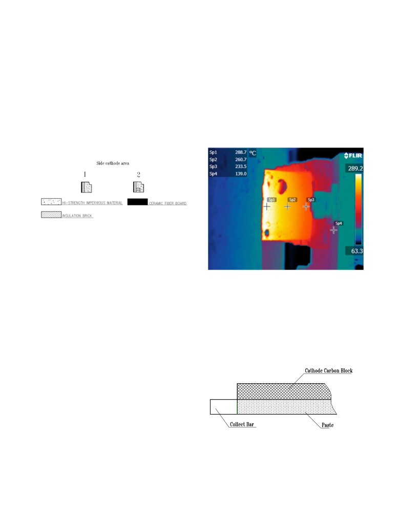
Overheated steel collector bars started to be observed in many
In conclusion, the top & bottom material combination option 1 is
large cells in recent years approaching 280 to 300 °C as can be
recommended for side wall area at liquids level for the cell
seen in the Figure 7 infrared picture. This problem leaded to
operating over 400 kA. Adding or not side wall high insulation
reconsider whether the 2 cm ceramic fiber board was desirable or
material depends on the selected cell operating voltage range.
not at that location. As per calculation, the influence on steel
collector bar temperature of the presence of that 2 cm ceramic
Side wall area at block level (pier region)
fiber board is about 10 to 15 °C. Again adding or not side wall
high insulation material depends on the selected cell operating
There are two mainstream design options for the pier region at
voltage range.
present, and they are as follow:
Figure 6: Side wall area at block level
With the prevailing low voltage cell operation, increasing the
thermal insulation of the cell in order to prevent excessive ledge
toe formation to get stable cell with high current efficiency is now
the main design focus for the pier region.
Figure 7: Infrared picture from thermal imager for steel
It shall be said that option 1, the combination of low strength
insulation bricks in the back plus high strength castable in front is
collector bar
the classic structure for the pier region. It is very mature and
efficient in both preventing metal infiltration and adsorbing stress
Collector bar assembly
from the cathode sodium expansion. For the low voltage cell
Another way to address the above overheated collector bar
operation, 2 cm of ceramic fiber board is added on the outer wall
problem is to work on the collector bar assembly design. Double
of the low strength insulation bricks, i.e. the combination of
ceramic fiber board in the back plus low strength insulation bricks
collector bars per block technology has now become very popular
in China.
in the middle plus high strength castable in front. That
combination has proven over time its efficiency to obtain stable
Typically ramming paste is used in China for the cathode block
low voltage cell operation.
collector bar connection as follow:
The difference between option 1 and option 2 lies in the addition
of clay semi-insulating refractory bricks. Those bricks have a
thermal conductivity of around
0.1~0.15 W/m2°C while the
thermal conductivity of high strength castable is about 0.3~0.5
W/m2°C. So, option 2 has a bigger inhibition on the ledge toe
formation. When considering a 420 kA cell operating at 0.78
A/cm2 for example, the ledge toe of option 2 is about 2~3 cm
shorter than that of option 1.
After actual verification on smelters operating using GAMI’s cell
technology, the cell current density has been increased steadily, so
the inhibition of option 2 on ledge toe formation is now too much.
Therefore, currently the semi-insulating refractory bricks in the
Figure 8: Full ramming paste connection
pier region have been removed and option 1 is preferred again.
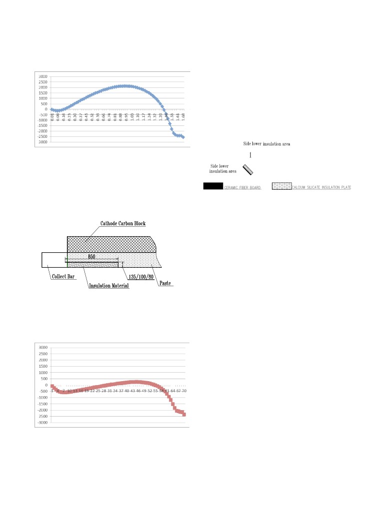
Calculation of metal pad horizontal current for double collector
In conclusion, double steel collector bar is better to restrain
bar connection for a 420 kA cell (current density 0.78 A/cm2) with
horizontal current in order to reduce bath-metal interface
bar section dimensions of 230 x 100 mm have been made, the
fluctuation. This increases cell stability and current efficiency.
results are as shown below:
This in turn allows to reduce the anode-cathode distance hence
lowering the cell working voltage.
Among the studied partial paste ramming connection design, the
one with the insulation part 80 mm high and 850 mm long prove
to be optimal to reduce the metal pad horizontal current.
Side wall area at lower insulation level
There is one mainstream design option for side wall area at lower
insulation level at present, as follow:
Figure 9: Metal pad JY for full ramming paste connection
Even with the ledge toe at its optimum position, this connection
design generates intense horizontal currents in the metal pad
which is bad for cell stability.
The usage of double bar technology is allowing the usage of
Figure 12: Side wall area at lower insulation level
partial ramming paste connection without changing too much the
cathode voltage drop as compared to the single bar as follow:
The side lower thermal insulation influences directly the ledge toe
extension. The design and choice of materials in this area has also
an importance to prevent metal infiltration. After many years of
trial and error on many projects, the relatively mature structure
has been established, as shown in the above figure. Considering a
420 kA cell operating at 0.78 A/cm2 for example, that design
option can reduce the ledge toe extension by 3~5 cm as compared
to the traditional dry barrier only design option.
In conclusion, the option 1 is recommended for side wall area at
lower insulation level for cells operating over 400 kA.
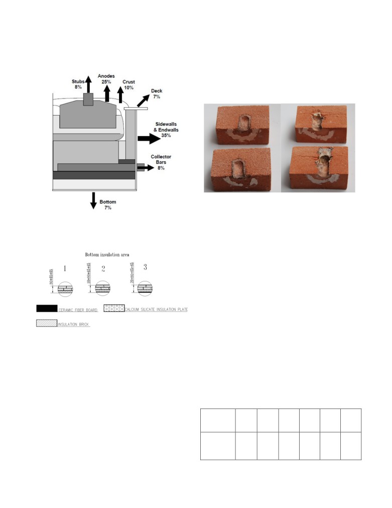
Bottom insulation area
Figure 10: Partial paste ramming connection [2]
The cell bottom insulation area is not considered important to be
If the optimum height of 80 mm of insulation material is used, the
able to decrease the cell heat loss in order to operate at lower cell
maximum metal pad horizontal current is decreased to 300 A/cm2
voltage. Indeed, as the cell bottom area is not dissipating a big
as opposed to 2200 A/cm2 in the previous case and the average
percentage of the total cell heat loss, it only represents about 6 to
value under the anode is 0 A/cm2 as shown below:
9 % for GAMI’s high amperage cell technology. Figure 13
illustrates a quite typical range that matches what has been
reported in the literature [3].
Cell bottom insulation area is ratter considered important for
keeping the cathode surface relatively clean. Good cell bottom
insulation can effectively prevent alumina and bath forming
sludge piles on the cathode surface, which is good for preventing
cathode drop increase caused by sludge. Hard crust will also form
on the cathode surface if the duration of cold cell bottom is too
long, which will cause abnormal cell operation, rapid decrease of
current efficiency, even safety accidents of “metal boiling” etc. in
extreme cases.
Many attempts, optimizations and laboratory tests have been
made in China in recent years based on the specific concerned
Figure
11: Curve Partial paste ramming connection
focus of proper cell bottom insulation. Optimum cell bottom
(insulation height 80)
insulation is of vital importance to safe and stable cell operation,
because enough bottom insulation is required to ensure good
working conditions of cell bottom under low voltage, but
heat dissipation is 6.5 % and the temperature on the top surface of
excessive bottom insulation must also be avoided in order to
the insulating brick is 825 °C.
prevent the isothermal curve to move too far down which
increases safety accidents from cell leakages, etc.
Vermiculite insulating brick is used on the surface row in option 3
instead of diatomite insulating brick because vermiculite
insulating brick has a better bath corrosion resistance than the
diatomite brick. Figure 15 shows the results of a bath corrosion
test.
Figure 15: Results of vermiculite (left) and diatomite (right)
insulating bricks corrosion test
Figure 13: Typical heat loss partition of high amperage cell [3]
For the vermiculite insulating brick, the hole diameter increased
There are three mainstream design options for bottom insulation
from 2 to 27 mm and the depth from 3 to 33 mm. The hole
area at present, as follow:
boundary is clear and bath corrosion was fully prevented. For the
diatomite insulating brick, the hole diameter is increased from 5 to
30 mm and the depth from 30 to 60 mm. The brick was seriously
corroded and that was accompanied by expansion and cracking.
The results of the test clearly indicate that vermiculite insulating
brick has a better bath corrosion resistance than that of diatomite
insulating brick.
Which option to use?
As the bottom insulation increases from option 1 to option 3, the
bottom heat dissipation decreases by about 2 % which is not a big
change for the cell heat balance. But the cathode surface increases
by about 2 to 3 °C, which is very important for keeping cathode
surface clean when the metal pad level is increased.
Figure 14: Bottom insulation area
With the large-scale development of the cell, the aluminum metal
Option 1 has 80 mm of calcium silicate board plus two rows of 65
pad level keeps getting higher and higher. This is required in order
mm of high strength insulating bricks from bottom to top.
to get high enough current efficiency. The following table shows
Considering a
420 kA cell
(current density of
0.78 A/cm2,
the relationship between cell current and metal pad level:
working voltage of
3.95 V) for example, the bottom heat
dissipation is 9 % and the temperature on the top surface of the
insulating brick is 800°C.
Table 2
Option 2 has 10 mm of ceramic fiber board plus 80 mm calcium
Relationship between metal pad level and cell current [1]
silicate board plus two rows of 65 mm of high strength insulating
brick from bottom to top. Taking the same 420 kA cell as an
example, the bottom heat dissipation is 7 % and the temperature
Current
300
350
400
420
500
600
on the top surface of the insulating brick is 820 °C.
(kA)
Option 3 has 20 mm of ceramic fiber board plus 80 mm calcium
Metal
silicate board plus two rows of 65 mm of high strength insulating
level
22
23
26
27
31
37
brick from bottom to top. For the same 420 kA cell, the bottom
(cm)
References
It is shown from the Table 2 that the cells over 420 kA must be
[1] Guo Hailing,
“Research & Application of Pot Horizontal
operated at a relatively high metal level. This means in turn that
Current”, IBAAS-CHALIECO International Symposium
the bottom insulation must be increased in order to prevent the
2013 Proceedings.
cathode surface to become too cold. The above three options are
suitable for different voltage cases, as the following table
[2] Zhou Jianfei, “A Kind of Cathode Assembly to Improve the
indicates:
Pot Stability, Increase CE, Reduce the Energy Consumption
and Prolong the Pot Life”, Chinese Patent: 201020504034.
Table 3
[3] Jay Bruggeman, “Pot Heat Balance Fundamentals”, Proc. 6th
Relationship between the bottom insulation design option
Aust. Al Smelting Workshop, 1998, 167-189.
and the cell operating voltage
Operating
voltage
4.05-4.15
3.95-3.85
3.75-3.85
(V)
Applicable
Option 1
Option 2
Option 3
option
The above three options are recommended for bottom insulation
area of the cells over 400 kA. Which is the most suitable depends
on the operating voltage range.
Conclusions
In general, the following recommendations and conclusions are
given for design options selection on different lining areas for the
cells over 400 kA:
• Side wall area at liquids level: the top & bottom
material combination option 1 is recommended for side
wall area at liquids level for cells operating over 400
kA. Adding or not side wall high insulation material
depends on the selected cell operating voltage range.
• Side wall area at block level (pier region): the option 1
is recommended for side wall area at block level (pier
region) of cells operating over 400 kA.
• Collector bar assembly: it is recommended to use
double steel collector bar connection with insulation
part 80 mm high and 850 mm long.
• Side wall area at lower insulation level: the option 1 is
recommended for side wall area at lower insulation
level for cells operating over 400 kA.
• Bottom insulation area: the above three options are
recommended for bottom insulation area of cells over
400 kA. Which is the most suitable depends on the
operating voltage range.