MODELING GRAVITY WAVE IN 3D WITH OPENFOAM IN AN ALUMINUM REDUCTION CELL
WITH REGULAR AND IRREGULAR CATHODE SURFACES
Marc Dupuis 1 and Michaël Pagé, Pr. Eng. 2
1 GéniSim inc., 3111 Alger St., Jonquière, Québec, Canada G7S 2M9
marc.dupuis@genisim.com
2 Simu-K inc., 188 Gobeil, St-Nazaire, Québec, Canada G0W 2V0
michael.page@simu-k.com
Keywords: Modeling, irregular cathode, cell stability, gravity wave, OpenFoam
Abstract
In any cases, as presented in last year review [2], it is the opinion
of the authors that a transient cell stability analysis is required to
In recent years extensive modeling work has been done to assess
make any prediction of the impact of irregular cathode surface
if the usage of an irregular cathode surface does or does not
technology on the cell stability as bath/metal interface wave
increases the MHD cell stability.
dynamic is a time dependant phenomenon.
So far, 2 types of studies have been carried out: full 3D steady-
As demonstrated in [2], MHD-Valdis is the perfect tool to model
state analysis and
2D shallow layer dynamic analysis. Cell
and hence study MHD driven cell stability in the case of regular
stability being a transient phenomenon, steady-state results are not
flat cathode surface as the model only represents and solves the
providing any direct answer to the question.
key physics required, nothing more, which make MHD-Valdis an
extremely efficient model.
2D shallow layer dynamic analysis can directly answer the
question, but unfortunately, irregular cathode surface introduces a
One of the key simplification in MHD-Valdis solver is the use of
third dimension to the flow, so this type of 2D analysis is not the
the 2D shallow layer CFD model to solve the bath and metal flow.
best suited to analyze this type of 3D flow problem.
Yet, as Figure 12 b) of [1] clearly demonstrates, for cells using
irregular cathode technology, this simplification is no longer valid
The current work presents a new way to analyze the problem and
as the flow is now fully 3D in nature.
answer the question. Lateral gravity waves have been simulated in
a 3D cell slice model using VOF formulation in OpenFoam.
MHD-Valdis also does not consider the impact of gas bubble
Results obtained for cells using regular and irregular cathode
release on the bath flow. This was demonstrated to be quite a
surfaces are compared.
valid simplification as it is clear that the dynamic of the gas
bubble release under the anodes, which strongly affects the global
Introduction
bath resistance, is decoupled from the cell stability problem.
Otherwise no cell stability model developed up to now would be
Irregular cathode surface technology is still the subject of research
valid.
in China where it is still quite popular. The most recent Chinese
paper known to the authors on the subject was published in
In [2] and in previous studies presented before that [3,4,5], MHD-
Metallurgical and Materials Transaction B in 2014 [1].
Valdis could not clearly show the impact of irregular cathode
technology on cell stability, maybe because of the
2D flow
That paper presents a very detailed 3D model based on ANSYS
structure simplification.
and CFX solvers. Four steady-state solutions are presented with
and without irregular cathode and with and without considering
Yet it is not by mistake that results of a full 3D transient MHD
the effect of the gas release under the anodes.
driven cell stability analysis was not presented in
[1]. Even
nowadays, CPU resources are still too sparse and too expensive
In addition to these four
3D steady-state solutions, two
2D
for such an analysis to be carried out without a huge R&D budget.
transient solutions were presented with and without irregular
cathode that model only the gas release.
The need for a third modeling approach
When comparing the two
2D transient solutions, no major
If reducing the metal flow to a shallow layer representation is not
difference in the global deformation or evolution of the bath/metal
a justified simplification in the case of irregular cathode surface
interface can be identified (see Figure 16 of [1]).
and if solving a full 3D transient cell stability problem is still not
practical, clearly there is a need to find a new modeling approach.
When comparing the two 3D solution of the conventional cathode
with and without the effect of the gas release, a major difference
There are two parts to the MHD driven cell stability issue: the
in the local deformation of the bath/metal interface in the small
energy source part coming from the presence of the variable
channel between anodes can be identified (comparing Figure 14 a)
Lorentz force in the metal pad as explained by Urata and
with Figure 28 a) of [1]).
Davidson among others [6,7] and the energy dissipation part
coming from viscous damping.
This local effect is far less intense in Figure 28 b) when compared
with Figure
28 a) for the irregular cathode which seems to
Clearly the aim of irregular cathode surface technology is to affect
contradict what is observed in Figure 16.
this second energy dissipation part by increasing the viscous
damping in the metal pad.
Yet for a bath/metal interface wave to move around, not only the
metal must be displaced but also the bath. Furthermore, since the
ACD layer thickness is much less than the metal pad thickness,
the required bath flow velocity needs to be much greater than the
required metal flow velocity.
So clearly, the viscous damping in the bath is very important and
must be considered in the analysis which will be the case in a 3D
analysis of the damping rate of a gravity bath/metal interface
wave in an aluminium reduction cell.
This approach reduces the difficulty of a study of the viscous
damping effect of irregular cathode surface which is perfectly
valid as this is the key effect that needs to be investigated.
Furthermore, if we choose to study a lateral gravitational wave,
the geometry of the problem can be reduced to a cell side slice as
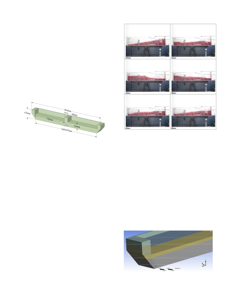
presented in Figure 1.
Figure
2: Experimental results for a free interface wave
Figure 1: Geometry of the cell side slice model
motion between two liquids in a closed container (Figure 16 in
[10])
OpenFoam and the free interface wave
Base case model setup
Even reduced both in terms of physic and geometry, we are still
left with a quite difficult question to solve namely a transient 3D
The geometry of the base case model, with regular flat cathode
multiphases (three in this case: metal, bath and air) flow. Very
surface was already presented in Figure
1. The model depth
few codes are able to cope with this problem, the open source
extends from a front frictionless symmetry plane located at half
code OpenFoam being one of them.
the anode width to the back frictionless symmetry plane located at
half width of the small channel between two anodes. The length of
OpenFoam has quickly become a very popular code in many
the model is typical of a cell cavity width minus a 10 cm uniform
fields such as marine applications due to its free surface modeling
ledge thickness in both ends: 3.94 m. The height of the model is
capabilities
[8]. Its free surface capabilities are comparable to
enough cavity depth to leave room for
20 cm of metal pad
other VOF solvers like CFX. A direct comparison between
thickness, 20 cm of bath thickness and 7.5 cm of air on top.
experimental, OpenFoam and CFX results for a free surface study
are presented in [9].
The model mesh is presented in Figure 3. The mesh is fine enough
to resolve fairly well the boundary layer problem close to the solid
The free interface wave between a gas and a liquid or between
surfaces
(cathode, ledge and anodes). It is constituted of
two non-miscible liquids in a closed rectangular container has
hexagonal finite volumes of approximately uniform size. The
been extensively studied experimentally, as can be seen per
mesh also perfectly aligned with the initial bath-metal position in
example in Figure 2, a reproduction of Figure 16 in [10]. As
order to have a perfectly smooth initial position of that bath-metal
explained in [11], it is very difficult to measure experimentally in
interface.
a reproducible manner the damping rate of such a gravity driven,
viscous damping wave problem.
Recently, OpenFoam has been quite successfully used to model
this type of free surface wave topic, per example [12] is a Ph.D.
thesis on the subject.
The problem of modeling the damping of a gravity bath-metal
interface wave in an aluminium reduction cell is a very similar
question with the extra difficulty that there are immersed anodes
in the top liquids and that it will be very difficult to get physical
measurements for model validation.
Figure 3: Mesh of the cell side slice model
The model contains
1,180,980 hex finite volumes with an
orthogonal quality of
0.77. It uses a k-ω SST
(shear stress
transport) turbulence model because of its demonstrated capability
to well predict drag [13].
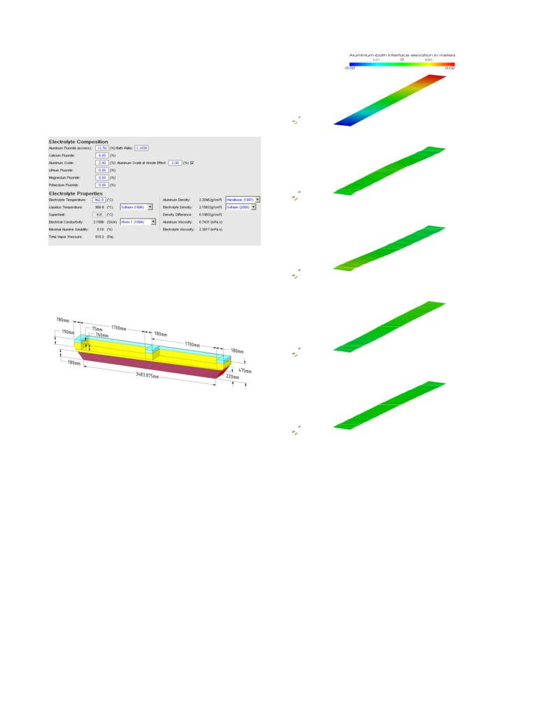
The bath and metal properties utilized where obtained using Peter
Entner’s AlWeb application
[14]. A quite standard bath
composition has been selected, see Figure 4.
Time: 0 second
Time: 15 seconds
Figure 4: Bath and metal properties from AlWeb
Time: 30 seconds
The transient evolution is starting from a resting position having a
sloped bath metal interface of -2 cm on the left side to +2 cm on
the right side as shown in Figure 5.
Time: 45 seconds
Figure 5: Initial bath-metal interface position
The transient evolution of the system from that starting point is
calculated using an explicit solver available in OpenFoam 2.3.0
[15], the multiphase Euler solver using a maximum courant
Time: 60 seconds
number of 0.05 and a maximum time step of 0.002 seconds.
Figure 6: Position of the bath-metal interface every 15 seconds
The transient evolution of the system was calculated for a total of
from 0 to 60 seconds
60 seconds which is more than 1 total period of the lateral wave
oscillation. The calculations were performed using a Dell 28 cores
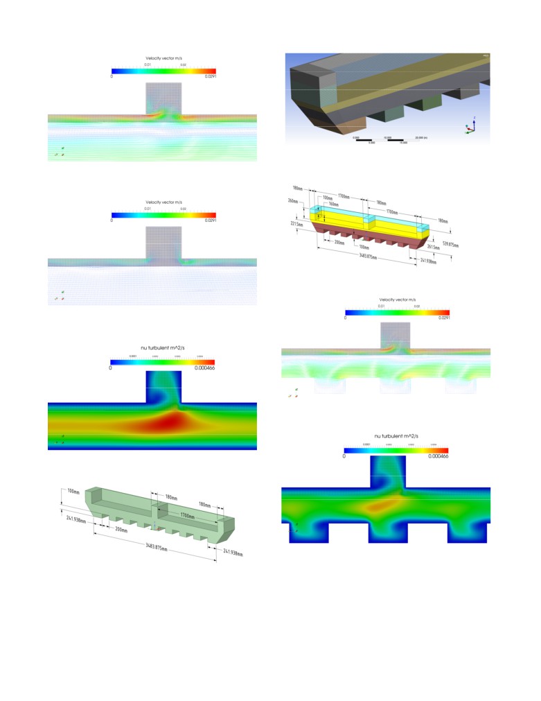
Figure 8 is showing the velocity field after 60 seconds, indicating
Xeon ES-2697 V3 computer having 128 GB of RAM at its
that the wave has been already almost completely damped down.
disposal. That computer took about 30 CPU hours to solve that
Figure 9 illustrates the turbulent viscosity after 15 seconds. Since
problem using all 28 cores.
the laminar viscosity of the metal is
3.224e-7 m2/s and the
maximum turbulent viscosity
4.66e-4 m2/s, the maximum
Base case model solution
turbulent viscosity is 1447 time the laminar viscosity.
Figure
6 is showing the position of the bath-metal interface
Irregular cathode surface case model setup
position every 15 seconds. That gravity lateral wave happens to
die almost completely in a single period.
The geometry of the irregular cathode surface case model is
presented in Figure 10. The geometry of the cathode surface has
The maximum velocity is reached a little before the 15 sec. mark.
been changed when compared to the base case model. But the
Figure 7 is showing the velocity field of the front plane. The
mass of metal, the mass of bath and the 4 cm ACD have remained
solver assumed continuity of the velocities at the interfaces so the
the same.
solution shows that the bath flow drags the top layer of the metal
so the flow reversal is occurring in the metal pad and not at the
bath-metal interface. The maximum bath velocity is about 3 cm/s.
Figure 11: Mesh of the cell side slice model with irregular
cathode surface
Figure 7: Velocity field after 15 seconds (bath region has gray
background)
Figure 12: Initial bath-metal interface position
Figure 8: Velocity field after 60 seconds (bath region has a
gray background)
Figure 13: Velocity field after 15 seconds (bath region has a
gray background)
Figure 9: Turbulent viscosity after 15 seconds (bath mesh is
visible)
Figure 14: Turbulent viscosity after 15 seconds (bath mesh is
visible)
Figure 10: Geometry of the cell side slice model with irregular
cathode surface
Due to the presence of the flow obstacles, the flow in the metal
pad is now quite different. Notice that flow around obstacles has
The model mesh presented in Figure 11 contains 1,152,016 hex
been extensively studied and successfully modeled using
finite volumes. Figure
12 is showing the initial bath-metal
OpenFoam [16]. Notice also that the mesh density used in [16]
interface position. Figures 13 and 14 illustrate the velocity and the
makes the one used in this study looking somewhat coarse!
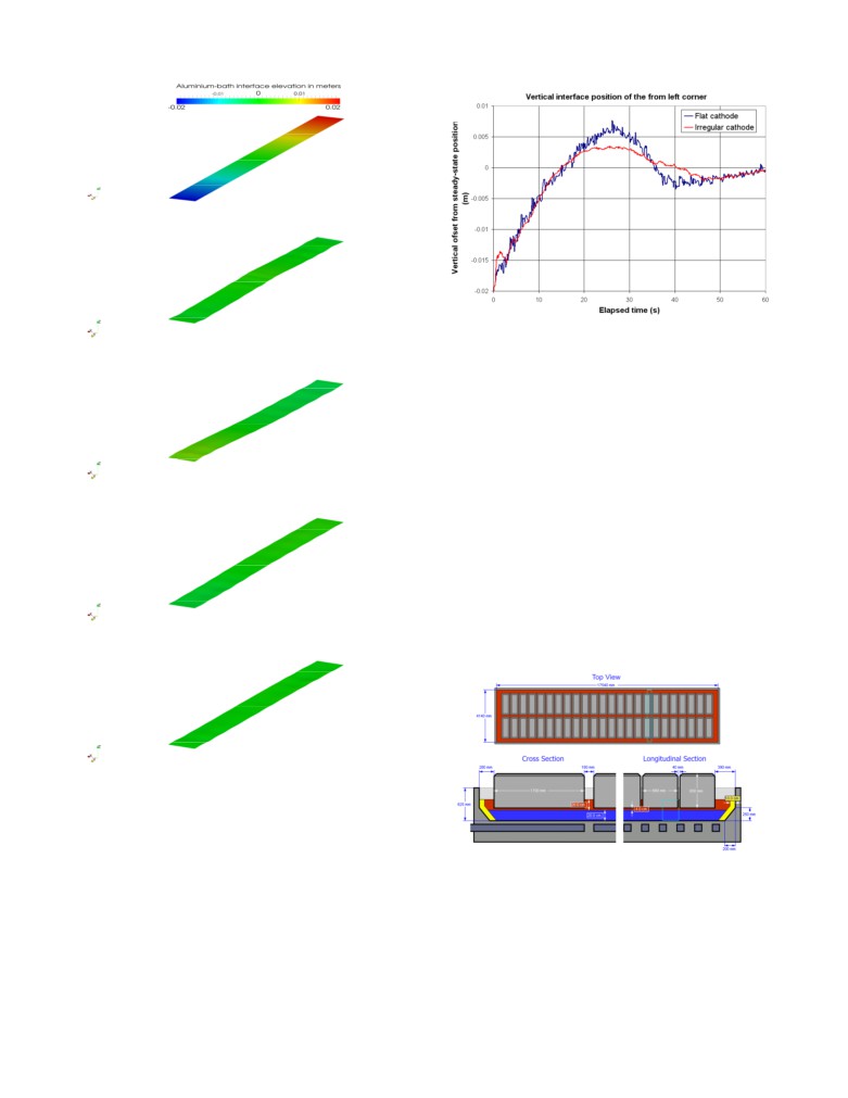
turbulent viscosity after 15 seconds. Figure 15 is showing the
position of the bath-metal interface position every 15 seconds.
Time: 0 second
Time: 15 seconds
Figure 16: Evolution of the interface front left corner
There is definitively less overshoot in the case of the irregular
cathode and also less secondary ripples on the interface so clearly
the obstacles are somewhat performing as intended [17].
Yet this observation is not in contradiction with what was
previously published in [2,3,4,5] in general and in Figure 7 of [5]
in particular. The damping effect of the irregular cathode surface
technology is not very important so many other changes to the cell
Time: 30 seconds
design can have more impact on the cell stability.
Future work
The geometry of the cell side slice model is coming from the cell
design presented in Figure
17 produced using Peter Entner
CellVolt application [18]. That cell geometry was inspired from
the GY420 420 kA cell design presented in [19]. Since that cell
design has 48 anodes, modeling a longitudinal gravitational wave
in a half cell model using the same mesh refinement used in that
Time: 45 seconds
study would require a model more than 24 times bigger. Even
with a linear increased of the required CPU time, solving such a
half cell slice model would require about 750 CPU hours which is
about 1 month of CPU time on the computer used in this study.
Time: 60 seconds
Figure
15: Position of the bath-metal interface every
15
seconds from 0 to 60 seconds
Comparison of the damping rate
The comparison between Figure
6 and Figure
15 interface
Figure 17: Sketch of the GY420 cell design that inspired the
positions reveals very little difference. Figure 16 is more useful
cell side slice model geometry
for that, for it shows the transient evolution of the vertical position
of the front left corner of the interface for the two cases.
A model optimization study might reveal that a coarser mesh and
a bigger time step could be used without losing much accuracy, so
performing such a model optimization would be important. Yet, it
is probable that a bigger computer than the Dell 28 cores Xeon
ES-2697 V3 computer used in this study would be required in
order to obtained a practical turn around time to solve a transient
[7] P. Davidson, “An Introduction to Magnetohydrodynamics”,
3D full cell gravitational wave VOF OpenFoam model.
Cambridge Texts in Applied Mathematics, Cambridge
University Press 2001, 363-386.
Adding the MHD physic to an even bigger 3D full cell OpenFoam
model is also quite possible to do. OpenFoam has already been
[8] H. Jasak, “OpenFOAM: Introduction, Capabilities and HPC
successfully used to solve MHD flows [20,21].
Needs”, Cyprus Advanced HPC Workshop Winter 2012.
Conclusions
[9] S. Hansch, D. Lucas, T. Hohne, E. Krepper and G. Montoya,
“Comparative Simulations of Free Surface Flows Using
Lateral gravity wave can be successfully simulated in a 3D cell
VOF-Methods and a New Approach for Multi-Scale
side slice model using VOF formulation in OpenFoam.
Interfacial Structures”, Proceedings of the ASME
2013
Fluids Engineering Division Summer Meeting.
Solving for just 60 seconds of transient evolution using a Dell 28
cores Xeon ES-2697 V3 computer took about 30 CPU hours.
[10] S. Y. Lee1, C. E. Park and V. H. Ransom, “On The Gravity
Driven Force Terms of Single Pressure One-Dimensional
Comparing regular flat cathode case model results with the
Multi-Fluid Flow Model in Horizontal Channel and Their
irregular cathode surface case model results revealed that there is
Validation”, Proceedings of ICAPP 2013 Jeju Island, Korea,
definitively less overshoot in the case of the irregular cathode so
April 14-18, 2013.
clearly there is somewhat more damping in that second case.
[11] D. R. Howell, B. Buhrow, T. Heath, C. McKenna, W. Hwang
Yet this observation is not in contradiction with what was
and M. F. Schatza,
“Measurements of Surface-wave
previously published using MHD-Valdis 2D shallow layer model
Damping in a Container”, Physics of Fluids, Vol. 12, no 2,
as this new study confirms that the extra damping effect of the
February 2000, 322-326.
irregular cathode surface technology is not that significant. Many
other changes to the cell design can have more impact on the cell
[12] G. C. J. Morgan, “Application of the InterFoam VOF Code
stability.
to Coastal Wave/Structure Interaction”, Ph. D. thesis,
University of Bath, Department of Architecture and Civil
A bigger computer than the Dell 28 cores Xeon ES-2697 V3
Engineering, September 2012.
computer used in the present study would be required in order to
obtain a practical turn around time to solve a transient 3D half cell
[13] F. R. Menter,
“Review of the Shear-stress Transport
VOF model to study a longitudinal gravitational wave.
Turbulence Model Experience from an Industrial
Perspective”, International Journal of Computational Fluid
Adding the MHD physic to an even bigger 3D full cell OpenFoam
Dynamics, Vol. 23, No. 4, April-May 2009, 305-316.
model is also quite possible to do. OpenFoam has already been
successfully used to solve MHD flows.
References
[1] Q. Wang, B. Li, Z. He and N. Feng,
“Simulation of
[16] I. Lindmeiera, C. Heschlb, G. Claussc and U. Heckd,
Magnetohydrodynamic Multiphase Flow Phenomena and
“Prediction of the Flow Around 3D Obstacles Using Open
Interface Fluctuation in Aluminum Electrolytic Cell with
Source CFD-Software”, The Fifth International Symposium
Innovative Cathode”, Metallurgical and Materials
on Computational Wind Engineering (CWE2010) Chapel
Transactions B, Vol. 45B 2014, 272-294.
Hill, North Carolina, USA May 23-27, 2010.
[2] M. Dupuis and V. Bojarevics, “Non-linear Stability Analysis
[17] N. X. Feng: Low Energy Consumption Aluminum Reduction
of Cells Having Different Types of Cathode Surface
Cell with Novel Cathode, China, ZL 200710010523.4, 2008.
Geometry”, TMS Light Metals 2015, 821-826.
[3] M. Dupuis and V. Bojarevics, “Influence of the Cathode
Surface Geometry on the Metal Pad Current Density”, TMS
[19] Ji-lin DING, Jie LI, Hong-liang ZHANG, Yu-jie XU, Shuai
Light Metals 2014, 479-484.
YANG and Ye-xiang LIU, Comparison of Structure and
Physical Fields in 400 kA Aluminum Reduction Cells, J.
[4] M. Dupuis and V. Bojarevics, “Newest MHD-Valdis Cell
Cent. South Univ. (2014) 21, 4097−4103.
Stability Studies”, Aluminium, 90 (2014) 1-2, 42-44.
[20] A. Panchal,
“Study of Liquid Metal MHD Flows Using
[5] V. Bojarevics, “MHD of Aluminium Cells with the Effect of
OpenFOAM”, AE 494:BTP Stage 2, Dept. Of Aerospace
Channels and Cathode Perturbation Elements,” TMS Light
Engineering, IIT Bombay.
Metals 2013, 609-614.
[21] E. Mas de les Valls, “Development of a Simulation Tool for
[6] N. Urata,
“Wave Mode Coupling and Instability in the
MHD Flows Under Nuclear Fusion Conditions”, Ph. D.
Internal Wave in the Aluminum Reduction Cells”, TMS
thesis, Dept. of Physics and Nuclear Engineering Universitat
Light Metals 2005, 455-460.
Polit`ecnica de Catalunya, October 2011.