
Computation of accurate horizontal current density in metal pad using a full quarter cell thermo-electric model
Marc Dupuis GéniSim Inc. 3111 Alger St., Jonquière, Québec, Canada G7S 2M9 email:
ABSTRACT
The computation of the current density in the metal pad is not required to assess the cell heat balance. So, it is not computed in standard thermo-electric models (1). Yet, the horizontal current density in the metal pad may have a significant impact on the cell stability.
For that reason, a version of a full quarter cell thermo-electric model has been extended in order to compute them as part of the solution. Results are presented for different ledge profiles obtained from running the cell at different levels of internal heat.
INTRODUCTION
It is well known that the Hall-Héroult process is very complex. For that reason, designing a new cell involves addressing successfully different key challenges:
| · | the cell must be able to dissipate the internally produced heat while maintaining a safe layer of side ledge protection; |
| · | the cell must not amplify small bath-metal interface perturbations into "noisy" stable long traveling waves; |
| · | the potshell must maintain its structural integrity and not excessively deform under both its thermal load and its carbon blocks sodium expansion load. |
Typically, those challenges are addressed separately as follow:
| · | the cell lining is designed with the support of thermo-electrical models (1) that compute the cell heat balance; |
| · | the cell external busbar network is designed with the support of a cell stability model (2) that computes the cell magneto-hydro-dynamic (MHD) behavior; |
| · | the potshell is designed with the support of a thermo-mechanical model (3) that computes the potshell plastic deformation; potroom ventilation models could also be involved (4). |
Yet, as described rapidly in (5), those key challenges cannot rigorously be independently addressed because they are actually interrelated. So, in principle, all those challenges should be addressed together with the support of a big "multi-physics" unified model.
This is not a new idea (6), but so far, it has not been a practical one because such a model would require tremendous computer resources. This is still translating today into an excessive model development and model application costs.
But, as computer are getting faster and cheaper to use every day, and modern cell designs are at the same time getting more and more challenging (7), the above statement will not remain true much longer!
FULL CELL QUARTER THERMO-ELECTRIC MODEL
As a first step toward a big "multi-physic" unified model, it is not much more work to add the liquid zone to a full cell quarter thermo-electric model in order to compute the metal pad current density that is required to carry out cell MHD stability analysis (see model mesh in Figure 1).

Figure 1: Full cell quarter thermo-electric model mesh
It is also possible to use ANSYS® to compute the magnetic field and hence the Lorentz force, but it requires the remeshing of the steel shell with brick elements and the meshing of the full smelter busbar network and of the air around the cell (8). Clearly, this second step is a lot more demanding both in terms of model setup time and model solution time and it requires a more expensive ANSYS® license. This second step was not performed in the present study.
In Figure 2, we can see the obtained voltage and current density in the metal pad for the converged ledge profile of this base case run characterized by an operation at 7 ºC liquidus superheat.
As we will see below, the current density in the metal pad is quite affected by the ledge profile and also by other aspects of the cell lining design. As we know that strong horizontal currents are bad for the cell stability, it is certainly appropriate to use metal pad current density as one of the criteria to assess the value of a given cell lining design.
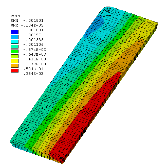

Figure 2: Full cell quarter model; voltage and current density in metal pad
CATHODE QUARTER + LIQUID ZONE THERMO-ELECTRIC MODEL
Considering that the above model is fairly big and that the anode panel solution is not required to converge the ledge profile, the current density solution of the full cell quarter model is compared with the one obtained with a smaller cathode quarter + liquid zone model (see mesh in Figure 3).

Figure 3: Cathode quarter + liquid zone thermo-electric model mesh
In this type of model (first presented in ref. 9), the liquid zone and the immersed part of the anode panel are added to the cathode mesh. As boundary condition, the voltage is set to zero at the top of the immersed part of the anodes. If this simplification is acceptable, we should obtain a very similar metal pad current density solution compared to the previous one without having to solve for the anode panel at each step of the ledge profile convergence loop.
As we can see in Figure 4, the metal pad current density is quite similar to the one obtained by the full cell quarter model for the same base case run. For this reason, all the following case studies will be run using the smaller cathode quarter + liquid zone model.
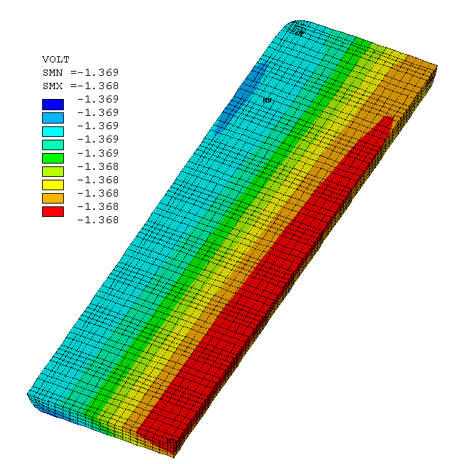

Figure 4: Cathode quarter + liquid zone model; voltage and current density in metal pad
CASE 1: RODDING COLLECTOR BARS UP TO THE EDGE OF THE BLOCKS
Before running cases to compare the impact of the cell superheat (ledge thickness) on the metal pad current density, it is considered appropriate to first modify the base case run by rodding the collector bars up to the edge of the cathode blocks. By doing so, the impact of the ledge position on the metal pad will be more pronounced.
Figure 5 presents the obtained current density in the metal pad. As we can see, for the same cell superheat (ledge thickness), the horizontal current density has increased by 18% simply because the cast iron rodding has been extended up to the edge of the blocks.
Since more horizontal current density translates into a less stable cell, this is already a clear example that the lining design can have a non-negligible impact on the cell stability. Furthermore, this is also an example of interrelation since the position of the edge of the cast iron rodding has also an obvious impact on the cathode drop and hence on the cell heat balance.
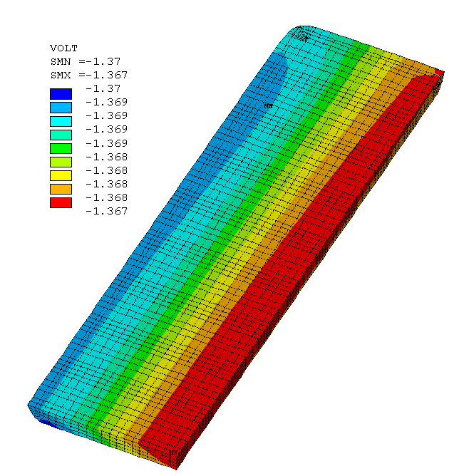

Figure 5: Case 1; voltage and current density in metal pad
CASE 2: DECREASING THE LIQUIDUS SUPERHEAT TO 5ºC
Decreasing the cell superheat by 2ºC has a major impact on the cell heat balance and the corresponding average ledge thickness. The idea here is not to evaluate if the cell would be thermally balanced at that superheat but rather to check what would be the impact of that extra ledge thickness on the metal pad current density.
As we can see in Figure 6, the increase of the ledge thickness has a huge impact on the maximum current density in the metal pad in the cell corner. Of course, this type of local ledge thickness increase in corners can only be predicted by a corner/quarter thermo-electric model (10). This is why the impact of such a metal pad current density is rarely analyzed in regular MHD cell stability studies.
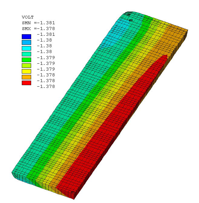

Figure 6: Case 2; voltage and current density in metal pad
CASE 3: INCREASING THE LIQUIDUS SUPERHEAT TO 9ºC
Inversely, increasing the cell superheat by 2ºC reduced the ledge thickness to the point where there is almost none felt above the big joint at the metal level.
As we can see in Figure 7, the removal of the ledge on the top edge of the cathode blocks significantly increased the intensity of the horizontal current in the bulk of the metal pad.
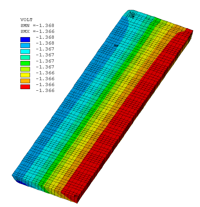

Figure 7: Case 3; voltage and current density in metal pad
CASE 4: LOW CATHODE BLOCK EROSION PROPOSAL
In reference 11, a change of lining design has been proposed in order to reduce the rate of cathode block erosion, the idea being that since the erosion rate is proportional to the current density at the surface of the block, a more uniform current density will translate into a lower maximum erosion rate. The same lining design is run here to analyze what will be the corresponding metal pad current density.
As expected, we can see in Figure 8 that this lining design, aiming at improving the cell life by reducing the maximum cathode block erosion rate, is also greatly reducing the horizontal current in the metal pad.
As a consequence, we can expect to get a significant improvement in the corresponding cell stability, clearly demonstrating again the link between cell lining design and MHD cell stability.
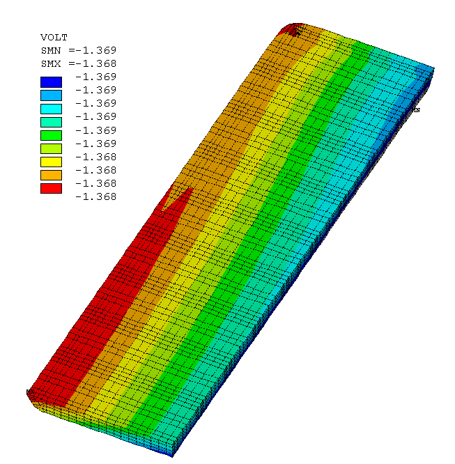

Figure 8: Case 4; voltage and current density in metal pad
CONCLUSIONS
A typical quarter cell thermo-electric model has been successfully extended to study the impact of the cell lining design and the cell operating conditions on the horizontal current in the metal pad.
The results clearly demonstrate that the maximum value of the horizontal current in the metal pad is strongly affected by the cell lining design and the cell operating conditions.
Considering the above, it is hard to believe that the cell stability problem is not significantly affected by the cell lining design and the cell operating conditions and that it can only be reduced to a busbar network design issue.
REFERENCES